

- Documentation
- Table of contents
- AKC
- Introduction
- Airframe Creation
- Technological Problems
- Experimental plant
- Building plant
- Conf. Development
- Aerodynamic Designing
- Algorithms of control
- Guidance & control
- Stand for training
- Training center
- Horizontal flight tests
- Crew on board
- Auto Landing complex
- Structure
- Payload bay
- Metallic material
- Non metallic material
- Non metallic material
- Cabin assembly
- Thermal designing
- Thermal protection
- Heat protection
- Quartz fibre
- Computer designing
- Gas's dynamic
- Strength
- Basic direction
- Tech. preparation
- Technical diagnostics
- Methods & means
- Radio nav. support
- Information & controls
- Control of onboard equ.
- Electric power dist.
- Electromagnetic
- Antennas installation
- Auxiliary power unit
- Hydraulic system
- Cabin
- Safety
- Air transportation
- Automatic landing
- Exp. working out
- Return to space
- SPIRAL
- Analysis of concept
- Horizontal take-off
- BOR-4 & BOR-5
- MAKS multipurpose
- MAKS-D
- Thermal design
- Gas & thermal design
- Wing deflection
- Flight performance
- Maks structure
- Metal materials
- Advanced non metallic
- Information provision
- Onboard starting comp.
- Onboard control comp.
- Control organization
- Aerospace systems
- Economic investigations
- Triplane aircraft
- Technical inventions
- Scientific potential
- Triumph and tragedy
- Birds of a Feather?
- TsAGI wind tunnel
- Bibliography
| -The Mriya is destroyed. |
| -Shipping of Buran-KS to Sotchi. |
| -Antonov is no more. |
| -Buran is now a museum. |
| -New pictures of the blogger Ralph Mirebs. |
From SPIRAL to MAKS
The MAKS Orbital Plane’s Wing Deflection as a Means of the Aerodynamic
Optimization on All Modes of the Flight
Terekhin V.A.
The effect of deflection of the wing panels of the MAKS Orbital Plane on its aerodynamics is considered. Using results of tests in wind tunnels it is presented the characteristics of Stability, Lift Capacity and Lift-to-Drag Ratio as a function of the wing panels angle. There is shown possibility of application of the wing deflection to satisfy the requirements for the various modes of flight.
It is well known that at the beginning of ENERGIA-BURAN reusable aerospace system development two alternative schemes of aerodynamic configuration design of the orbital plane were considered – winged scheme, similar to the Space Shuttle spaceship system, and ‘lifting body’ scheme with small wing panels. The latter scheme has been used for the last ten years by SPIRAL project under the direction of G.E. Lozino-Losinsky for design and experimental development in design bureau of A.I. Mikoyan, TsAGI, LII and other organizations. Because of several reasons the winged scheme was chosen for the BURAN orbital plane. It was successfully realized by NPO MOLNIYA in cooperation with many other enterprises.
Nevertheless, the ‘lifting body’ idea has found its implementation in the following project of NPO MOLNIYA – reusable aerospace system (MAKS), namely in the orbital plane of this system.
The Major Trends of MAKS Aerodynamic Development
It is natural that MAKS project was based on scientific and research achievements had created by the beginning the MAKS project in aerospace techniques. As an example, the SPIRAL orbital plane, itself can be mentioned as its contours and some configuration solutions were initially used for the MAKS orbital plane. Also it is necessary to indicate MRIYA (AN-225) plane created as a plane for transportation of the elements of ENERGIA-BURAN system (the orbital plane and rocket launcher’s elements) and further transformed into a carrier-plane for MAKS project. This list can be continued. At the same time all predecessors of the MAKS system represent considerably more complicated system as from general technical point of view and as from aerodynamics. In aerodynamics it is essential to solve the following large problems:
- achievement of high lift-to-drag ratio for the carrier-plane with large-size external superstructure fixed on it – the orbital plane with external fuel tank (OPET);
- aerodynamics of joint flight and separation of the carrier-plane and the orbital plane with a tank considering influence of jets from main propulsion unit of the orbital plane;
- maintenance of stability and controllability of the orbital plane with a tank by means of the main propulsion unit and declined aerodynamic surfaces on the injection trajectory (including abnormal situations);
- determination and optimization of lift capacity of the orbital plane with a tank and distributed aerodynamic loads on configuration elements at maximum dynamic pressure on injection trajectory at subsonic velocity and big attack angle – to increase system performance;
- maintenance of high lift-to-drag ratio for the orbital plane of ‘lifting body’ configuration at hypersonic and landing flight modes;
- maintenance of static aerodynamic stability of the orbital plane along three axis for descending trajectory.
Along with the complicity of the MAKS aerodynamics it is necessary to mention such factors as multi-element structure of the system and multi-mode flight of its elements which determine necessity of large-volume multi-parameter experimental researches in wind tunnels. These researches are directed on aerodynamic configuration processing and receiving initial data for the following elements of designing chain (system and construction).
The most part of research and calculation works as well as tests in wind tunnels on all development phases of MAKS system was conducted by NPO MOLNIYA in close cooperation with TsAGI on its experimental base.
It is also necessary to indicate several tunnel experiments made in SibNIA and ITPM SO, the institutes from Academy of Sciences of the USSR. These experiments, as it was set up from BURAN project, were conducted in advance with application of models made in SibNIA institute. Among important research studies of TsAGI and NPO MOLNIYA we would like to mark the wing profiles optimization and orbiter bottom pressure study which considerably improved landing performance. The researches on fillet between external fuel tank and MRIYA carrier-plane for improving of lift-to-drag ratio and on pressure distribution along orbital plane and external fuel tank surfaces and methodical testing of ‘jet’ models and several others are worth mentioning.
The mentioned-above aerodynamic problems are still in development phase at the moment. As one of solved problem we can mention maintenance of high hypersonic lift-to-drag ratio. The external contours of the MAKS orbital plane at the very beginning were similar to the SPIRAL orbital plane contours. However, maximal lift-to-drag ratio (CL/CD) was quite low because of high dulling of fuselage nose. That didn’t permit to achieve enough lateral maneuver required at various MAKS missions. Taking into account this circumstances, TsAGI suggested to extend length-diameter ratio of the plane and as much as possible reduce dulling radius of fuselage nose. That would have allowed to increase (CL/CD)max at hypersonic descent leg up to 2.5 (indicated hereinafter CL/CD values and other aerodynamic performance were received as results of tunnel testing of corresponding aerodynamic models). As a result of further development conducted by NPO MOLNIYA, the contours of the orbital plane were formed and approved. They are still the same now with several small modifications. The hypersonic value of (CL/CD)max for completely approved aerodynamic configuration of the orbital plane was 2.0…2.2. This value is higher than in the cases of SPIRAL (1.4) BURAN (1.8) orbiters.
MAKS Orbiter’s Aerodynamic Stability
Another problem, also successfully solved during MAKS project development and considered in details below, was to guarantee static aerodynamic stability of the orbital plane in accordance with attack angle and especially in accordance with side slip angle on every flight modes.
It is necessary to indicate that by the beginning of the MAKS project development activity on the BURAN orbital plane was in full wings. Special studies were conducted to eliminate all discovered weak spots including those in aerodynamics. One of the most important questions that required great attention was to maintain aerodynamic stability and controllability of the orbital plane at different angles of attack and side slip angles for hypersonic and supersonic descent trajectory modes. The tunnel experiments and design researches showed that though dynamic stability of the orbital plane was high for such velocity range acceptable characteristics of lateral motion could be realized only when reaction control system (RCS) was on.
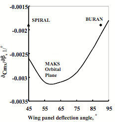
Taking into account insistent need of ilateral motion characteristics improvement for the MAKS orbital plane, it was natural to consider previous experience. The idea was to install deflected wing panels on the orbital plane as it had been done in SPIRAL project: deflection angle ψpanel = 45° at hypersonic and supersonic modes (in present paper the term ‘wing panel deflection angle’ means an angle between plane of panel and vertical axis of the orbital plane). Such decision gives us possibility to solve simultaneously a problem of temperature on wing panels. Experimental researches in wind tunnels showed that wing panel deflection at ψpanel = 45° guaranteed static aerodynamic stability for the whole range of hypersonic and supersonic velocity.
|
|
Figure 1. Rolling stability of the orbital plane as a function of the wing panel angle: |
М = 7…10 and α = 40°
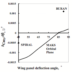
This position of wing panels guaranteed static stability for any attack angles in operational range. Hence, aerodynamic configuration of the MAKS orbital plane guarantees its stability in all three axes. It is appeared that stability and controllability characteristics were higher than the same characteristics of the previous projects. This fact is shown on Figure 1 and Figure 2 where side slip angle (β) derivatives of lateral aerodynamic moments of the SPIRAL orbital plane, the BURAN orbital spaceship and one of the predecessor of the MAKS orbital plane are depicted. The latter models were thoroughly studied in wind tunnels to determine the wing deflection influence on aerodynamics of the orbital plane at hypersonic and supersonic flight velocity.
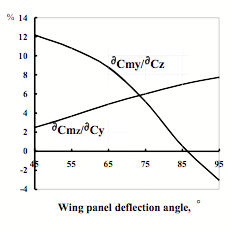
Relative contribution of wing panels lift capacity to longitudinal aerodynamics is higher than to lateral one because aerodynamic configuration of the orbital plane was fulfilled in accordance with ‘lifting body’ scheme. The results of tunnel tests, depicted on Figure 3, shows, as the angle of wing panel deflection is reduced from ψpanel = 95° to ψpanel = 45° at considered flight modes the changes in reserves on yawing and pitching static stability of the orbital plane differ in three times - 15% и 5% accordingly.
|
|
Figure 2. Yawing stability of the orbital plane as a function of the wing panel angle: |
М = 7…10 and α = 40°
The tunnel researches also showed that maximum lift-to-drag ratio was reduced at that approximately for 0,2 (i.e. for 10%) and at angles of attack of α = 30…50° corresponding to the descent trajectory – even less.
Thus, the researches shows that for supersonic and hypersonic flight velocity wing panel installation in a ‘fin’ position with wing panel deflection angle ψpanel = 45° completely solves a problem of stability in lateral direction.
|
|
Figure 3. Reserves on rolling and yawing stability as a function of the wing panel angle |
М = 7…10 and α = 40°
|
|
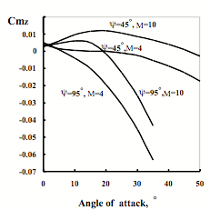
Figure 4. Wing panel angle influence on pitch moment at supersonic and hypersonic velocity |
At the same time when ψpanel = 45° losses in lift-to-drag ratio and longitudinal stability are acceptable.
It is necessary to emphasize that at considered flight modes the wing panel deflection angle reduction leads to the general reduction of dependence between lift capacity of the orbital plane and angle of attack in longitudinal channel and to the increase in dependence of side-slip angle in lateral channel. The latter change leads to the displacement of aerodynamic focuses of normal and lateral forces. That’s why in contrast to the control devices of usual planes (rudder, elevons, flaps and other), which deviations lead to small alteration of aerodynamic moments weakly dependent from attack and slip angles, wing panel deflection angle alteration mainly changes the aerodynamic focuses location. This results in the changes of aerodynamic moments and effects on stability.
This method is quite flexible for controlling of aerodynamics of the orbital plane and its optimization. So that in particular at the displacement of the center of gravity during development phase conservation of hypersonic auto-balancing at certain angle of attack required only wing panel deflection change for several degrees without change of margin on construction and internal composition. This decision was based on the corresponding design estimations received from experimental data as well as on the estimation of temperature on the panels, which showed possibility of such action.
The wing panel deflection may be used for auto-balancing angle alteration at supersonic and hypersonic velocity. This fact is illustrated by Figure 4.
It was shown in experimental researches in wind tunnels that a change of aerodynamics of the orbital plane as a function of wing panel deflection was more complicated at transonic and subsonic speed.
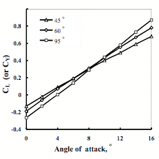
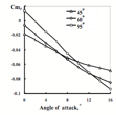
Panels shift to the ‘fin’ position (ψpanel = 45°) from the ‘wing’ position (ψpanel = 95°) is accompanied by lift capacity and stability reserves increase on 2…5%. At such conditions dependencies between aerodynamic lift (CL or CY) and pitch moment (Cmz) coefficients and attack angle are turned around at angle of attack α = 10° and balancing of the orbital plane at flight mode isn’t changed for different wing panel deflection angles (Figures 5 and 6).
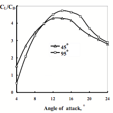
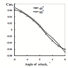
Maximum lift-to-drag ratio for landing modes at changing of deflection angle from ψpanel = 45° to ψpanel = 95°, as it is for hypersonic modes, increases approximately on 10% (Figure 7) and value of CL coefficient – on 5…10%. At the same time at the whole subsonic range of Mach numbers (from landing value to M = 1) – yawing stability practically isn’t changed at deflection angle alteration (Figure 8), though rolling stability is considerably increased at wing panel deflection angle ψpanel reduction.
Indicated factors show irrationality and even undesirability to leave hypersonic position of wing panels while flying at subsonic and transonic speed. It is desirable and even obligatory to install corresponding system for transferring of wing panels from hypersonic ‘fin’ position into subsonic ‘wing’ position. It guarantees coordination of hypersonic and subsonic aerodynamic characteristics of the orbital plane and its aerodynamic optimization on the whole.
|
|
Figure 5. Orbiter’s lift capacity as a function of the wing panel angle at transonic velocity: М = 1 |
|
|
Figure 6. The effect of wing panel angle on pitch angle at transonic velocity: М = 1 |
Aerodynamics of the MAKS second stage as a function of the wing panel angle
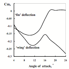
One more successful application of wing panel deflection has become formation of acceptable moment characteristics of the orbital plane with a tank when injecting at transonic speed. Requirements on injection trajectory of the orbital plane with a tank say in particular that pitch aerodynamic moment at such velocity should be zero and even slightly positive.
|
|
Figure 7. The wing panel angle effect on lift-to-drag ratio at the landing velocity |
|
|
Figure 8. Orbiter’s yawing stability plane as a function of the wing panel angle at transonic velocity: М = 1, α = 10° |
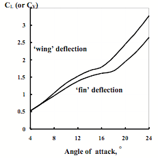
These requirements were completely satisfied by wing panels installation in a ‘fin’ position. If there was relatively big distance between wing panels and center of gravity of the orbital plane with a tank, ‘fin’ deflection was accompanied by a slight lift capacity reduction (in comparison with ‘wing’ deflection). It was entirely compensated by optimization of propulsion unit thrust vector re-direction with consideration of longitudinal balancing.
|
|
Figure 9. The wing panel angle effect on lift capacity of the MAKS orbiter with external fuel tank at transonic velocity: M = 1,1 |
The influence of wing panels deflection on transonic aerodynamics of the orbital plane with a tank is shown on Figures 9 and 10.
The wing panels installation in ‘fin’ position also improves yawing stability of the orbital plane with a tank, especially at supersonic speed when as it was mentioned above the panels start to work as fins. Besides, the improvements in aerodynamics, the wing panels installation in ‘fin’ position, which corresponds to the descent of the orbital plane at hypersonic speed makes easier the exploitation excepting necessity of their re-installation at the orbital conditions. Thus the coordination of descending and injecting modes of the orbital plane is performed.
The Alteration of the Wing Panel Angle at Accurate Definition of the MAKS Aerodynamics
The wing panel deflection (i.e. fitted in construction principal possibility of their installation in a certain position) was and is a fine tuning method to change aerodynamic composition during further scientific and research development. And what is more the fin control systems developed lately on the basis of new technologies allow to decline two-position panel deflection widely used in the today’s orbital planes and pass to the systems of their continuous re-positioning during the flight. Such systems guarantee optimal aerodynamic performance in every particular point of the trajectory. This circumstance was thoroughly considered when the MAKS project was still in development.
|
|
Figure 10. The wing panel angle effect on pitch moment of the orbiter with external fuel tank at transonic velocity: М = 1,1 |
All basic composition modifications of the orbital plane were put to the wind tunnels for researching of influence made by wing panel deflection on the aerodynamic characteristics. At that specialists in aerodynamics had to overpass resource shortage and even organization problems. But nowadays NPO MOLNIYA has large experimental database, containing the information on how wing panel deflection influences on aerodynamics of the MAKS orbital plane. The part of it is used as illustrations for the present paper. Such statement at a great extent determines many other questions concerned MAKS aerodynamics. It guarantees a possibility of gradual completion of the design researches and transition to the development project.
The present paper doesn’t cover problems with controllability and stabilization of angular motion by means of elevons placed on the wing panels in ‘fin’ position. As domestic and foreign experience confirms, the creation and development of control system algorithms for such aerodynamic composition is more complicated. However, the advanced characteristics of MAKS stability and successful cooperation with other organizations during development of the BURAN orbital plane give us a hope for solving mentioned-above problems as well as many other providing effective, reliable and safe functioning of the MAKS system on the whole.
The application of the aerodynamic composition of the MAKS orbital plane with deflected wing panels allowed to solve stability and controllability problems at descent and landing as well as at injecting of the orbital plane with a tank into an orbit. At that a fine tune methods of aerodynamics alteration are foreseen at the development phase.