
- Documentation
- Table of contents
- AKC
- Introduction
- Airframe Creation
- Technological Problems
- Experimental plant
- Building plant
- Conf. Development
- Aerodynamic Designing
- Algorithms of control
- Guidance & control
- Stand for training
- Training center
- Horizontal flight tests
- Crew on board
- Auto Landing complex
- Structure
- Payload bay
- Metallic material
- Non metallic material
- Non metallic material
- Cabin assembly
- Thermal designing
- Thermal protection
- Heat protection
- Quartz fibre
- Computer designing
- Gas's dynamic
- Strength
- Basic direction
- Tech. preparation
- Technical diagnostics
- Methods & means
- Radio nav. support
- Information & controls
- Control of onboard equ.
- Electric power dist.
- Electromagnetic
- Antennas installation
- Auxiliary power unit
- Hydraulic system
- Cabin
- Safety
- Air transportation
- Automatic landing
- Exp. working out
- Return to space
- SPIRAL
- Analysis of concept
- Horizontal take-off
- BOR-4 & BOR-5
- MAKS multipurpose
- MAKS-D
- Thermal design
- Gas & thermal design
- Wing deflection
- Flight performance
- Maks structure
- Metal materials
- Advanced non metallic
- Information provision
- Onboard starting comp.
- Onboard control comp.
- Control organization
- Aerospace systems
- Economic investigations
- Triplane aircraft
- Technical inventions
- Scientific potential
- Triumph and tragedy
- Birds of a Feather?
- TsAGI wind tunnel
- Bibliography
| -The Mriya is destroyed. |
| -Shipping of Buran-KS to Sotchi. |
| -Antonov is no more. |
| -Buran is now a museum. |
| -New pictures of the blogger Ralph Mirebs. |
BURAN Orbital
Spaceship Airframe
Creation
Air Transportation
Dr. Fedotov V.A.
On the basis of comparing different ways of transportation the blocks of the launcher and Orbiter’s airframe of ENERGIA-BURAN complex to the launching site the economic feasibility of air transportation application is justified. Technological problems which arose at transformation of 3M bomber into ATLANT VM-T transport airplane, and ways of their solution are considered. The possibility of using the air transportation of bulky cargoes, components of advanced aerospace systems, and heavy equipment for different branches of the national economy is shown at their external arrangement on the carrier-plane of increased weight-lifting capacity.
Hundreds major plants participated in creation of ENERGIA-BURAN system, and the manufacturing of the rocket launcher and orbiter’s airframe was distributed among them. It has created a serious problem on choosing the places of these parts assembly and delivery to the starting point, to the launching site. Initially, it was offered to concentrate the basic manufacturing process of assembly in Baikonur, however, it was recognized inexpedient, since it required the organization of high capacity industrial departments engaging a great many of qualified specialists. Only the final assembly and pre-launch working-out were decided to be carried out at the launching site, whereas the basic scope of assembly works was to be executed at the major factories.
Air means versions of the airframe delivery have appeared more preferable. The manufacturers of the launcher came to the same decision. Two versions of air transportation were considered: helicopter and aircraft.
The newly developed MI-26 helicopter of the weight-lifting capacity of 26 tons was offered for delivery by helicopter. According to this project, bulky cargoes of high mass (airframe and rocket bays) tied with cables had to be carried by 2 or 3 helicopters, and such ‘bundle’ had to move along the route, at the best fit height and flying speed. As the basis for such version the example of helicopters application for ‘crane’ operations was brought, but there was still no experience of flights ‘in bundles’.
Test flights with mock-up cargo having the configuration of a tank section of the rocket were carried out at LII. The tests revealed a complexity and risk of such kind of delivery. During one of the flights at a suddenly arisen weak turbulence of atmosphere, a ‘pendulous’ swing of cargo on the cables started which caused a disturbance of the helicopters flight stability, owing to what the crews were compelled to dump the cargo.
The calculation estimation has shown that such situation is probable in the future flights and at more intensive disturbances of atmosphere it can entail disastrous consequences. The failure of this version was also caused by economic unfeasibility of its application: helicopters capabilities of only short range non-stop flight with cargo on suspension would require creation of numerous landing fields with refueling stations arranged along the line.
AN-124 RUSLAN airplane was intended for aircraft delivery of bulky fragments of ENERGIA-BURAN system. However this airplane was still under construction at that time. It was possible to take it into account only in the long term, and it was necessary to search for other capabilities. There was the initiative of General Designer V.M. Myasischev who proposed to transform 3M airplane, a strategic bomber in the past, into a cargo plane. This airplane had a high lift-to-drag ratio necessary for accomplishment of long-range flights, which could be offered at its re-equipment into transporter for cargoes.
Two versions of its modification were considered. The first version was with arrangement of cargoes inside the increased cargo bay of the fuselage (of Galaxy airplane type). It required a creation of new fuselage of increased diameter (10 m instead of 3 m which 3M airplane had). At that BURAN airframe had to be transported with detached wings (BURAN span of wings is 24 m), which provided a partial removal of tiles from heat-protection coating. The bicycle undercarriage of 3M airplane was to be replaced with tricycle. In the total, the structural airplane mass increased, owing to what its weight-lifting capacity was decreased. But, in general, the term of cargo version manufacturing became unacceptable. Second version proposed by General Designer V.M. Myaschischev was a bomber with smaller alterations, namely with arrangement of cargoes outside the airframe, ‘on top’ of fuselage, which allowed to convey cargoes with minimum change of their configuration. The idea of the conveyed freight arrangement outside of aerodynamic contours of the plane was basically not a new one. Such solution is widely used in military and civil transport aircraft of all countries. The novelty consisted in exotic ratio between the overall dimensions of the cargo and the carrier-plane (diameter of tank sections of the rocket was 8 m, while the diameter of airplane fuselage was 3 m).
It is known, that at external arrangement of effective load, the aerodynamic and mass-inertial characteristics of any flying vehicle essentially vary, serious studies of motion dynamics and safety control of maintenance are carried out for estimation of the flight performances varying because of it. The problems to be solved at implementation of V.M. Myasischev’s proposals were much more complicated than the conventional ones.
It was necessary to change the geometry of 3M airplane in such a way that all freights of a new system intended for air delivery could be placed on its airframe. At that the installation of each particular cargo aboard the plane so considerably changed its aerodynamic characteristics and elastic-mass scheme, that the flying vehicle of essentially new aerodynamic and dynamic layout was organized. In this connection there was a necessity to repeat all researches on aerodynamics and strength conducted earlier for 3M airplane at its creation.
General Designer Myasischev’s proposals were skeptically met by many specialists. There were serious grounds for doubts. How is it possible to allocate on the ready-made airframe the freights exceeding its overall dimensions? How can the sharp drag increase be overcome without aggravating the basic flight performances of the airplane? Will it be possible to handle the plane’s controls and to provide the lateral stability during the flight in the presence of a destabilizing action from the freights allocated on top? How can the risk of tail unit buffet be eliminated, which was displayed in the flight of Boeing-747 with Space Shuttle spaceship? For 3M airplane this phenomenon could become even more dangerous. And at last, whether the construction of a plane, which was exploited for more than 25 years in the long-range aviation, is capable to maintain the loading in new operation conditions, if it already has numerous fatigue damages?
The main of the adopted design solutions, as it was indicated above, was the sacrifice of a part of high lift-to-drag ratio of the ultra-long-distance plane (CL/CD max = 18.5). It was explained by the increase in drag because of the cargoes ‘on the top’. It was allowable, since the distance of cargo transportation was preset shorter, than the available flight range of 3M plane. The flight speed, which was necessary to decrease because of cargoes installation, favorably reduced loads and improved the safety from flutter. The positive factor for the benefit of 3M-airplane transformation into carrier-plane was its undercarriage of a bicycle configuration with supplementary bolstering racks on the wings’ edges.

|
|
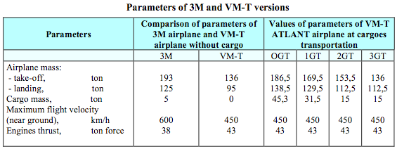
Parameters of 3M and VM-T versions |
Such scheme provided motion stability on the ground at a cross wind and protected the plane from being upset by forces which were acting on the cargo placed above the fuselage. The buffet phenomenon was supposed to be maximally softened by replacement of a single-finned vertical tail unit with twin-finned.
The design of 3M airframe was carefully studied during all 25 years of maintenance. Three airplanes passed repeatedly the static structural tests in SibNIIA during this time, by their results, the strength of planes in operation was monitored. They should help to find the solutions on replacement or strengthening the most important elements of the airplane’s structure in the view of new conditions of their loading. It was supposed to provide a steady and controlled flight with modification of control system. Certainly, the detail studies of all versions of dynamic scheme of the airplane (with different cargoes) for determining the loading of elastic construction and provision of safety against flutter and buffet.
The transformation of 3M airplane into cargo transporter VM-T ATLANT (factory code 3-35) demanded the introduction of the changes in its layout, which would permitted to place all preset cargoes in a complete set:
- OGT - BURAN Orbiter airframe (without a fin);
- 1GT - hydrogenous tank of the central stage of ENERGIA rocket launcher with nose and aft cowl;
- 2GT - oxygen tank, instrumental and propulsion bays, forward part of the central stage of ENERGIA rocket integrated in one unit with a nose cowl disassembled into sections, and forward part cone used as tail cowl;
- 3GT – forward and aft cowls of cargo 1GT, connected in one unit with allocated inside disassembled into section forward cowl 2GT.
3GT cargo was used as a container for the cowls return from launching site to the manufacturing plants for repeated use, and in necessity of transportation of cockpit module.
Consequently, VM-T ATLANT had to be operated in five different versions of layout: four - with cargoes OGT, 1GT, 2GT, and 3GT; one - without cargoes (so-called ‘autonomous’ version).
The parameters of all versions of VM-T ATLANT airplane (mass, flying speed, engines thrust) in comparison with the characteristics of 3M plane are listed in the Table.
Cargoes arrangement ‘on the top’ of the airplane became possible after fuselage elongation by 4.7 m, which was carried out by replacement of rear bay slightly elevated due to ‘oblique’ insertion in order to prevent the impact with the ground at landing and take-off with big angles of attack. Studies of stability and controllability resulted in necessity of change of dimension and shape of all surfaces of the tail unit. Due to decrease of flying speed, the stabilizer of the swept horizontal unit was replaced with the straight line one, of larger area established with a high dihedral. Instead of a single-finned vertical tail unit, a considerably increased (up to 26% of wing area) twin-finned unit was established. It was made as two washers obliquely fixed on the edges of the stabilizer, which promoted the decreasing of loads acting on the fuselage.
Neither sizes nor shape of the wing and other part of fuselage (including cockpit) were subject to changes, as well as the nose and main rack of the bicycle undercarriage. The outriggers of the undercarriage were designed anew and manufactured for the increased loads arising for the plane with cargoes at landings with a roll and taxiing on the launch site. The load-bearing structures of wing and fuselage were strengthened for loads determined by the new operation conditions. The necessary adaptations were entered into the fuel system of the plane. 15B engines were replaced with more powerful 17D engines.
For acceptance of five layouts of the airplane, the researches on aerodynamics, stability and controllability of flight were conducted. For each version of cargo its optimal arrangement on the fuselage (by length and height) was determined, proceeding from the following conditions:
- drag decrease;
- constraints on the moment characteristics dispersion;
- obtaining the necessary center-of-gravity positions;
- attenuation of dynamic effect of vortex sheet descending from cargoes and gas jets of engines on the tail fins (buffet).
It was established that the main carrier characteristics CL = f(), at the brought-in changes into layout, were practically kept for all versions. As expected, the maximum lift-to-drag ratio has essentially (by 30…35%) decreased. The increased aerodynamic moments arising from large freights (1GT and 2GT) were compensated by the mentioned introduction of the direct stabilizer of the greater area. The destabilizing lateral effect from the cargoes was completely parried with end-plate fins. Their excessive area at flight without cargoes demanded to introduce a special automatic device into control ensuring the necessary stability and controllability. Research of an aerodynamic interference between the airplane and cargoes was carried out, which revealed a picture of distribution of local air loads on the surface of fuselage and cargoes. Studies of strength have allowed to ensure the minimum expenditures of weight for the change of airframe design and simultaneously to solve the problem of aero-elasticity. This was promoted by the accepted decrease of flying speed decreasing the design loads. The permissible for the crew maneuverable normal g-loads were constrained by the values:
ny max <= 1,5; ny min = 0.
With the purposes to increase the safety of maintenance, the larger design values of normal g-loads were accepted:
ny max = 1,5; ny min = 1.0.
At determination of dynamic loads and researches on flutter, the materials obtained for heavy airplanes at OKB Myasischhev were used in 50s. The dynamic loading of the tail part of airplane from ‘buffets’ was examined in wind tunnels of a TsAGI and SibNIIA and was monitored at flight tests of the first sample of airplane. Was proved that the safety from buffets is provided for all versions of VM-T. Strains in the construction of tail unit and fuselage at buffet appeared in the limits, not dangerous for fatigue strength.
The strength of undercarriage (main and under-wing) was checked by static and dynamic tests.
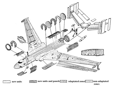
One of the main problems of using the units of 3M-airplane airframe for VM-T airplane was the updating their design for maintenance of safe operation. For the substantiation of service life of the preset VM-T airplane, together with scientists of TsAGIs and SibNIIA the calculations were executed and the special tests of the modified construction with considering the previously executed studies of three airframes of 3M- airplane were conducted. The volume of the brought-in changes into the longitudinal frameworks of the wing and fuselage is shown in Figure 1.
The adaptation of the design was inspected by the full-scale static tests of the airframe. To provide needed strength for cargoes was the task for cargoes’ developers.
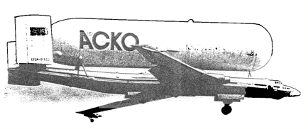
VM-T ATLANT airplanes executed more than 150 flights on transportation of cargoes of ENERGIA-BURAN system (Figure 2). The experience obtained at their creation has appeared useful for further use in the promising airspace programs.

|
|
Figure 1. Adaptation of VM-T airplane structure |

|
|
Figure 2. VM-T transporter plane with tank section of ENERGIA rocket launcher on external suspension |

|
|
Figure 3. Transportation of BURAN Orbiter by AN-225 MRIYA airplane |
Possible reduction of scope of works in Baikonur and beginning of development of launchers of the greater weight-lifting capacity on the basis of ENERGIA rockets modification have made to search for ways of essential increase of weight-lifting capacity of means of air delivery. VM-T ATLANT airplane can transport cargoes of up to 50 tons mass, and for perspective developments the mass of cargoes can exceed 200 tons. The project required for this plane-transporter was worked out together with OKB named after O.K. Antonov.
On the basis of the designed project the modification of AN-124 airplane was conducted, and on its base AN-225 MRIYA transport airplane of weight-lifting capacity up to 225 tons on the external suspension is created. For the first time it took-off in December, 1988, and in 1989 executed BURAN transportation (Figure 3) to the Aviation Show in Le-Bourget (France) and later on - some demonstration flights to Europe and America.
The maintenance experience of VM-T ATLANT and AN-225 MRIYA airplanes has proved the concept of creation of complex layouts of flying vehicles including the bulky components with essentially different aerodynamics, mass and rigidity characteristics. The work on such projects has determined the direction of researches for choosing their positional relationship ensuring a minimization of structural mass and exclusion of ‘parasitic’ influence of interference between the docked objects on aerodynamic forces and the moments in all modes of operation.
The creation of MRIYA airplane was consequently the basis for development of a reusable two-stage aerospace transport system and the project of HERACLES heavy transport airplane.
The designed and implemented systems of air transportation can find application in the most different branches of the economy, having provided the air transportation of bulky cargoes to the remote regions of Russia.