
- Documentation
- Table of contents
- AKC
- Introduction
- Airframe Creation
- Technological Problems
- Experimental plant
- Building plant
- Conf. Development
- Aerodynamic Designing
- Algorithms of control
- Guidance & control
- Stand for training
- Training center
- Horizontal flight tests
- Crew on board
- Auto Landing complex
- Structure
- Payload bay
- Metallic material
- Non metallic material
- Non metallic material
- Cabin assembly
- Thermal designing
- Thermal protection
- Heat protection
- Quartz fibre
- Computer designing
- Gas's dynamic
- Strength
- Basic direction
- Tech. preparation
- Technical diagnostics
- Methods & means
- Radio nav. support
- Information & controls
- Control of onboard equ.
- Electric power dist.
- Electromagnetic
- Antennas installation
- Auxiliary power unit
- Hydraulic system
- Cabin
- Safety
- Air transportation
- Automatic landing
- Exp. working out
- Return to space
- SPIRAL
- Analysis of concept
- Horizontal take-off
- BOR-4 & BOR-5
- MAKS multipurpose
- MAKS-D
- Thermal design
- Gas & thermal design
- Wing deflection
- Flight performance
- Maks structure
- Metal materials
- Advanced non metallic
- Information provision
- Onboard starting comp.
- Onboard control comp.
- Control organization
- Aerospace systems
- Economic investigations
- Triplane aircraft
- Technical inventions
- Scientific potential
- Triumph and tragedy
- Birds of a Feather?
- TsAGI wind tunnel
- Bibliography
| -The Mriya is destroyed. |
| -Shipping of Buran-KS to Sotchi. |
| -Antonov is no more. |
| -Buran is now a museum. |
| -New pictures of the blogger Ralph Mirebs. |
BURAN Orbital
Spaceship Airframe
Creation
Structure of the BURAN Orbiter
Dr. Tarasov A.T.
The paper discusses some features of BURAN Orbiter’s structure, defined by the exploitation conditions and the demand to minimize its mass. Technical ideas to solve the problems faced are covered. The possibility to use them in developing future reusable aerospace systems is also shown.
The BURAN Orbiter is designed as a winged craft close in shape to a high-speed heavy wide-fuselage tailless airplane with a low wing aspect ratio.
The Orbiter’s airframe is injected into an orbit as part of a rocket-launcher (RL) of a complicated package layout. When in an orbital flight the Orbiter is a satellite. When descending it is gliding automatically and overcomes the thermal barrier. Then it makes a pre- landing maneuver, approach and landing. When gliding, BURAN overcomes a sequence of speeds from orbital to hypersonic, supersonic, transonic and subsonic.
Such numerous functions of the Orbiter made it difficult to develop its structure. It should meet the inevitable demand for all the flying vehicles: minimal structure mass and secure provision of strength.
The service conditions and functions of the airframe at all the flight stages have result in its differences from a traditional heavy plane layout.
The Blunt of BURAN Nose and Wing Leading Edges
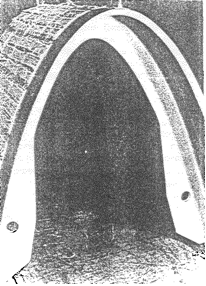
Considerable radius of the nose part and the leading edges (Figure 1) of the wings provided appropriate temperatures at the entry and descent flight in dense atmosphere.
The surface temperatures of these structural elements are of 1400…1500°C re. To provide reusability, the leading edges were made of the GRAVIMOL carbon-carbon heat protection material with a special coating (the name GRAVIMOL is composed of initials of the manufacturer enterprises: NII GRAFIT, VIAM, and NPO MOLNIYA).
Heat Protection Tile Coating
To maintain thermal conditions of the airframe’s service it is coated with protective tiles. The Orbiter’s framework is exposed to numerous deformations. Meanwhile the ceramic heat protection tiles are made of silicon dioxide fiber and should be placed as closely as possible, without touching each other at the hull’s deformations. To save the entirety of the heat protection at the airframe deformations special filling of heatproof felt has been introduced. The 0.8-mm gaps between the tiles save them from destruction. The felt is glued to the tiles and the metal skin with the ELASTOSIL glue.

|
|
Figure 1. BURAN Orbiter’s wing leading edge after static tests. |
BURAN Orbiter’s Attachment to the ENERGIA Rocket Launcher
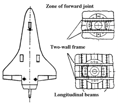
The effect of big concentrated forces is transferred to BURAN Orbiter’s airframe via three points of attachment to the ENERGIA launcher. The nose attachment point transfers only vertical and longitudinal forces, whereas the two tail points transfer vertical, latitudinal, and longitudinal forces. Most considerable are longitudinal and vertical forces reaching 500...600 of per a point at maximal wind effect and launcher’s thrust.

|
|
Figure 2. BURAN-to-ENERGIA attachment points. |
To distribute these forces in the airframe an installation of two double-walled bulk heads in the nose and tail parts and two longerones in the aft part of the Orbiter’s fuselage (Figure 2).
The Crew Cockpit (Cabin)
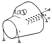
To provide decent thermal and acoustic conditions the cockpit (cabin) module is suspended on special rods (Figure 3). Such design also excludes deformations of the cockpit’s module when the nose part is loaded. Double shell, double glass fitting, special attachment points – all this brought about increases in the Orbiter’s mass.
Doors of the Payload Bay
The 18 meter-long bay in the body’s upper part required the usage of doors, opening in an orbit. Their total area is 144m².
The doors are of a semi-frame structure, i.e. they participate in transferring longitudinal forces, but don’t transfer forces of bending moment. This has required the usage of a complicated structure. 8 parts, joined up by special rods, cut each door. The rods only transfer shifting forces. All the door parts are attached to the fuselage and to one another by hinges and locks, incorporated into a complex controllable structure.
For more details on the solutions realized in the doors’ design see the separate paper on them in this book.

|
|
Figure 3. Cockpit (cabin) module attachment to the nose part of fuselage |
Besides the features described above which are defined by the Orbiter’ service functional conditions there are other features caused by the demands of weight minimization.
Truss Structures
Construction heights of fuselage and wing lower parts are above 1.5 m. At such heights and comparatively low loads a truss is optimal to accept the shearing forces in the wing spars and ribs and the fuselage bulk heads. The optimization of VT-20 titanium alloy welded rods lead to the creation of rods with varied cross section (Figure 4).
Double-Walled Frames
The installation of double-walled frames in the application points of concentrated big forces (launcher attachment points) provided moment-free transiting of forces to the walls of the frames. Besides, longerones cross lower booms of the frames on different levels. All this lowered the mass of structural members.
Nose Attachment Point
The location of nose attachment point was chosen rationally – it is located near nose landing gear strut. The same frame accepts the loads in two cases planned: flying attached to the launcher when injected into an orbit and from the undercarriage when landed.
Composite Materials
The use of KMU-4E composite material for the cargo compartment doors decreased their mass by 700 kg compared to a duralumin structure. This is another evidence of the rationality of using composites. For more information on the use of composites see the paper ‘Non-Metal Materials’ of this book.Even now most ideas used in BURAN are undoubtedly new and may be used in development of reusable aerospace systems of the future.

|
|
Figure 4. The rod as apart of truss construction |