
- Documentation
- Table of contents
- AKC
- Introduction
- Airframe Creation
- Technological Problems
- Experimental plant
- Building plant
- Conf. Development
- Aerodynamic Designing
- Algorithms of control
- Guidance & control
- Stand for training
- Training center
- Horizontal flight tests
- Crew on board
- Auto Landing complex
- Structure
- Payload bay
- Metallic material
- Non metallic material
- Non metallic material
- Cabin assembly
- Thermal designing
- Thermal protection
- Heat protection
- Quartz fibre
- Computer designing
- Gas's dynamic
- Strength
- Basic direction
- Tech. preparation
- Technical diagnostics
- Methods & means
- Radio nav. support
- Information & controls
- Control of onboard equ.
- Electric power dist.
- Electromagnetic
- Antennas installation
- Auxiliary power unit
- Hydraulic system
- Cabin
- Safety
- Air transportation
- Automatic landing
- Exp. working out
- Return to space
- SPIRAL
- Analysis of concept
- Horizontal take-off
- BOR-4 & BOR-5
- MAKS multipurpose
- MAKS-D
- Thermal design
- Gas & thermal design
- Wing deflection
- Flight performance
- Maks structure
- Metal materials
- Advanced non metallic
- Information provision
- Onboard starting comp.
- Onboard control comp.
- Control organization
- Aerospace systems
- Economic investigations
- Triplane aircraft
- Technical inventions
- Scientific potential
- Triumph and tragedy
- Birds of a Feather?
- TsAGI wind tunnel
- Bibliography
| -The Mriya is destroyed. |
| -Shipping of Buran-KS to Sotchi. |
| -Antonov is no more. |
| -Buran is now a museum. |
| -New pictures of the blogger Ralph Mirebs. |
From SPIRAL to MAKS
The MAKS Onboard Control Complex
Dr. Balashov M.P., Gordiyko S.V., Karimov A.G.
Main principles and structure of the MAKS Onboard Control Complex are considered. The problems of diverse onboard equipment research are analyzed. The comparative analysis of the Federal Decentralized and Centralized structures of the Onboard Computer Complex is conducted. Advantages of the Federal structure are justified. The characteristics of the Onboard Computer and structure of the Information Exchange between systems are considered.
The on-board control complex (OCC) of the MAKS reusable aerospace system is high-integrated hardware and software complex providing object motion control and on-board systems’ interaction on all flight phases: from take-off with the carrier-plane (CP) to race and stop on a runway.
Carrying out the indicated functions, the on-board control complex solves the following major tasks:
- to perform automated control of on-board systems in normal and abnormal situations and to form separation commands for a given connection stage in accordance with a given MAKS preparation and flight program (jointly and after separation);
- to control and diagnose technical state of on-board systems, to manage information exchange between interacting systems and to form information blocks transmitted into earth and into storage devices;
- to re-configure on-board systems at failures during the flights, to turn off broken blocks and to turn on reserve blocks instead of broken ones;
- to perform automatic control of center of mass motion of MAKS elements on injection, orbital and descending legs as well as during a run on runway up to full stop;
-
to provide:
- required stability and controllability performances and prevention of entrance to critical motion parameters,
- determination, processing and distribution among consumers of information concerned general and aviation parameters for all MAKS flight legs,
- shaping of breaking impulse at descend preparation.
The MAKS on-board control complex (OCC) in autonomous mode forms aviation parameters with precision required for controlling motion trajectory and automated airdrome landing on all flight trajectory.
Aboard of MAKS the orbital plane the following tasks are settled:
- stabilization and motion control;
- spatial navigation and orientation control;
- information displaying and control interaction with a pilot;
- acquisition and processing of telemetry information and transmission of telemetry information, interaction with ground-based flight supporting facilities by radio link.
The structure of the on-board control complex is based on the following principles:
- hierarchy;
- modularity of OCC hardware and software allowing to distribute development works and reduce development period;
- functional and hardware reservation to achieve required parameters of system survivability, reliability and fault-tolerance;
- utilization of multiplexed data communication channels for mass reduction of on-board cable system;
- utilization of computer equipment based on custom-designed microchips which at maximum extent allow to reduce mass and dimensions as well as power consumption of OCC equipment;
- advanced control and diagnose system, application of expert system principles for developing of mathematical software.
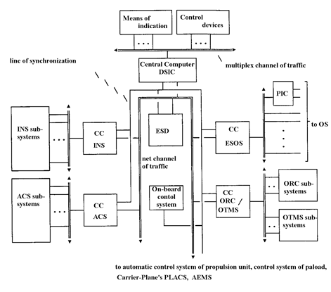
The indicated principles and features of OCC structure is realized in federal decentralized structure of on-board computer system (OCS) and interfaces used in OCC. The MAKS on-board control complex (Figure 1) includes the following functional systems:
- on-board computer system (OCS);
- navigation complex (NC) which consists of automatic control system (ACS) and informational navigation system (INS);
- executive system of on-board systems (ESOS);
- control and diagnose system (CDS);
- display system for information and controllers (DSIC);
- on-board telemetry measure system (OTMS);
- on-board radio complex (ORC).
OCC interacts by network adapter with automation of engine unit, payload control system, preparation and launch automated control system (PLACS), ground-based control facilities – automated experimental mobile station (AEMS).
OCS is intended for information stream distribution between OCC systems, interconnecting of functional systems, execution of mathematical software (MS) and system synchronization.
The MAKS navigation complex (NC) performs task solution for every flight legs and consists, in its turn, of informational navigation system (INS) and flight automatic control system (ACS). The INS forms navigation parameters required for MAKS task solution on every flight legs. The ACS performs task solution of automatic control of flight for separation, injection, orbital, atmosphere entering, descending, pre-landing maneuvering, approaching and landing legs of flight and run on a runway till full stop.
The executive system of on-board systems (ESOS) is software and hardware complex providing control of on-board systems’ (OS) functioning and supervision of their working for all MAKS flight legs.
The control and diagnose system (CDS) performs controlling, diagnosing and forecasting of technical state of MAKS on-board systems during flight and ground testing.
The major interaction facility between a crew and on-board complex is display system for information and controllers (DSIC) which depicts motion and navigation parameters in automatic, semi-automatic and manual modes for crew members.
The on-board telemetry measure system (OTMS) is used for obtaining of measured information at processing, testing and MAKS exploiting. The OTMS is a complex of on-board and ground-based facilities providing granting of measured information to different consumers in a more convenient way for perception and further analysis.

|
|
Figure 1. The on-board control complex (OCC) structural scheme with interacting systems |
To transmit aboard of the orbital plane radio control commands from the ground in abnormal or emergency situations it is supposed to use on-board radio complex (ORC).
A pre-flight control test of on-board equipment and launch from mobile start are performed at interactions between OCC and ACSLPL.
OCC units heterogeneous devices in a single OCC complex executing mathematical software (MS) and perform following functions:
- interconnecting of functional systems;
- execution of mathematical software (MS) and operational logic of OCC at providing interactions of different systems by data communication channels;
- synchronization of execution of MS on different functional systems;
- information stream control between functional systems.
The range of possible structures of on-board OCS is limited, on the one hand, by decentralized (federal) structures and, on the other hand, by completely centralized structures.
In centralized structure of OCS the functions of central computer (CC) is quite complicated: it performs a processing of information received from navigation system (NS), complicated information processing, centralized automated control of all complex equipment, provides united indication and control and so on. Special requirements are presented for such central computer (CC) when it is necessary to realize such structure. The development process of software becomes more complicated as well.
The analysis of OCS centralized structure shows that it has following disadvantages:
- high requirements presented for CC (operating speed, memory size, data channel capacity and so on);
- complicity and awkwardness of software development;
- a necessity to debug and change mathematical software if only part of it is changed or modified;
- functional dependence and correlation of tasks solved.
The general disadvantage is impossibility to conduct parallel development and adjustment of separate subsystems of on-board equipment.
Multi-computer on-board complex application allows to eliminate disadvantages peculiar to OCS with central computer. At the same time application of such system is caused by rapid improvements in computer industry which reduces computer’s mass, dimensions and power consumption..
The major feature of federal decentralized structure of OCS is build-up independent systems equipped with separate computers. The main advantages of federal decentralized structure of OCS are:
- functional independence of solved tasks;
- optimal allocation of computer power for different functional tasks of subsystems and a possibility for separate system designers to choose computer equipment;
- high level of parallel calculations (at that there is no limitation on calculation speed which so frequently appears in centralized OCS);
- practically unlimited growing of complex total processing power at application of plain and cheap computer systems;
- less strict determination of designed computer power, possibility to change its volume and re-distribute it during detail planning;
- comparative simplicity of subsystem interfaces caused by low speed and number of signals transmitted between subsystems;
- parallel computation in different subsystems of OCC (due to that it is possible to achieve synchronous ending of development and adjustment of separate subsystems before their consolidation and adjustment on the whole);
- reliability increment by use of functional reservation methods without considerable complication of hardware;
- optimal co-existence of functional and hardware reservation and acceptable level of build-up control and diagnose software facilities;
- flexible OCC architecture and reservation permitting to re-configure system during flight.
The federal decentralized structure of OCC maximally meets MAKS requirements.
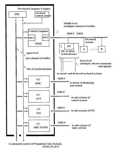
After adjustment and analysis of tasks solved by MAKS it is advisable to create OCC with central computers connected between each other by common network interface. They solve separate functional tasks in federal decentralized structure (see. figure 2).
The on-board synchronizer (OS) provides, in this structure, CC synchronization and generating of time intervals.
The external storage device (ESD) is used for storing of flight purpose, current and given parameters, separate software modules.
The multiplexed data communication channels (MDCC) are used for communication of CC with peripheral interface controllers (PIC) and interface blocks. The data exchange by channels (see. figure 1) is performed in accordance with GOST 26765.52-87 standard.
The PIC performs conversion of information transmitted from CC of ESOS by multiplexed channel. The single control command transmission from CC into on-board systems is performed by instruction issue (II) PIC and single signal from on-board systems to CC – by sensor inquiry (SI) PIC.

|
|
Figure 2. The on-board computer system (OCS) structure and information exchange scheme with on-board control complex (OCC) |
The information cable system is used to connect PIC with on-board systems. The initial deployment of on-board systems is performed on commands transmitted from II PIC. The control of on-board systems’ initial state (including, plug control) is performed through CI PIC.
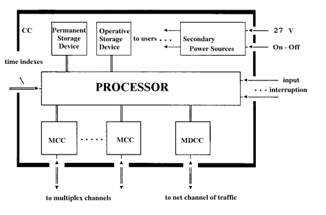
The CC of OCS includes (Figure 3):
- processor;
- operating (О) and storage (S) memory (M);
- network data channel controller (NDCC) and multiplexed channel controller (MCC);
- secondary power source (SPS). To choose CC it is necessary to follow mentioned below characteristics: data format - 32 bits, operating speed – not less than 1 million operations per second;
- storage device memory size – not less than 512 K byte;
- operating memory size – not less than 512 K byte;
- data communication channels – multiplexed and network;
- inputs – interruptions and time periods;
- mass – under 5 kg;
- power consumption – more than 30 W.
The chosen structure of OCS (Figure 2) determines three-layered scheme of intersystem data communication:
- the upper level – interaction of OCS functional systems by network channels;
- the medium level – connection between CC of each OCS functional system with interface blocks and PIC interacting by multiplexed data communication channels;
- the lower level – connection between PIC and sensors and devices of on-board systems (relay, analogue and other signals).
In ESOS the lower level of interfacing is provided by initial deployment of OCS systems.
Let’s see technical specification of OCS data exchange.
The upper level of information provision in OCS. The informational exchange between functional systems of OCS is performed by software control of information streams with time division by network data channel.
The consumers of the network data channel is CC of OCS functional systems: ESOS, DSIC, NC (ACS, INS), ORC/OTMS and ESD.
The informational exchange between CC is performed through interface with a use of redundant data exchange channels.
The information for the consumers from network data channel enters each reservation edge through separate informational channel in accordance with ‘channel-edge’ scheme. The informational output from the consumers to network data channel is performed from each reservation edge in separate informational channel in accordance with ‘edge-channel’ scheme.

|
|
Figure 3. The central computer (CC) structure |
The medium level of information provision in OCS. The informational medium-level exchange is provided by multiplexed information channels and is used to connect CC with on-board equipment and PIC. This level has the following features:
- interfacing with on-board systems is performed by redundant multiplexed data communication channels;
- on-board systems includes one or several interfacing blocks with access to multiplexed data communication channels;
- in some cases, standard peripheral exchange controllers can be used in capacity of interfacing blocks, and interfacing blocks of on-board systems can be exchanged on multiplexed channel adapters;
- data exchange procedure between CC and on-board systems is organized so that MMC of CC is always acting as a bus controller and multiplexed channel adapters from interfacing blocks of on-board systems and PIC are always terminals.
The lower level of information provision in OCS. The informational lower-level exchange is provided by PICs which interact with CC of functional systems by MDCC. PICs are standard devices developed for CC. The PICs transform digital information received from CC by MDCC and signals from on-board systems into a form required by on-board systems and CCs.
The consumer (PIC, interfacing block of onboard system) functions in the following way. CC forms command entered MDCC in a code equivalent, a consumer performs received command, namely: on-board system’s sensor status scanning or command transferring into an execution unit. After sensor scanning information is transferred into code and is transmitted into CC by MDCC.
When command is transmitted into on-board system, a consumer forms an response by MDCC (message) about execution in CC. The CC performs periodical control of consumer efficiency by examination of status registers available. The status registers store results of self-control performed by consumer facilities.
Separated CCs of OCS solve tasks of ESOS, DSIC, NC, ORC and OTMS.
The executive system of on-board systems (ESOS) is software and hardware complex providing control of on-board systems and flight modes during all flight legs and pre-start preparation.
The ESOS provides hard- and software as well as functional integration of on-board equipment and performs following functions:
- data exchange between functional systems of on-board radio equipment;
- on-board systems’ control in normal and abnormal flight modes;
- settlement of abnormal situations at failures of on-board systems.
The control and diagnose system (CDS) performs controlling, diagnosing and forecasting of technical state of MAKS on-board systems during flight and ground testing. The CDS performs following functions:
- generating and control of common parameters of on-board systems;
- failure searching in on-board systems;
- forecasting of technical state of on-board systems;
- information issue onto DSIC. Information describes technical state of on-board systems in a form of values of controlled parameters.
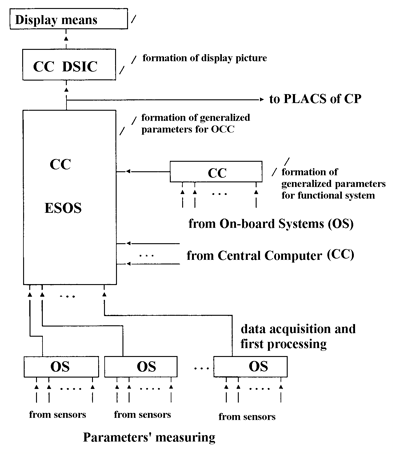
The CDS – functionally distributed system performing its functions by hardware facilities of controlled on-board systems (see. figure 4). The information from source information sensors of each on-board system can be transmitted into corresponding CC, directly or through interfacing blocks of on-board system which performs parameters’ preprocessing. The CCs of the functional systems perform on-board systems’ signal processing executing failure search algorithm, forecasting technical state of on-board systems and calculating secondary and common parameters of on-board systems and so on. The information issued for CCs of functional systems is received if necessary by PLACS of carrier plane for parameter registration and by CC of ESOS foe executing algorithms of upper-level CDS.
The CC of ESOS performs control and diagnose algorithms where analysis of technical state of different on-board systems is required. Besides, CC of ESOS uses control and diagnose information generated by CDS algorithms for automated control of on-board systems.
The CDS information can be used by ground-based control facilities during inter-flight service and routine maintenance.

|
|
Figure 4. The control and diagnose system (CDS) structure |
The conclusions
1. The up-to-date central computers (CC) allow to design the MAKS on-board control complex based on decentralization of computer equipment on functional levels, reduce designing and adjustment of equipment and mathematical software (MS) and efficiently carry out on-board equipment integration.
2. The decentralized federal structure of OCS of OCC allow to realize flexible, re-configurable at failures structure, increase reliability, operating sped and memory size of computer equipment.
3. Nowadays, the new principles of OCS organization is being searched. They will permit to increase system efficiency, reduce cost and optimize processing methods. Good prospects are connected with module principals of OCS and MS organization as well as with use of central computers with higher operating speed (tens million operation per second) and storage and operating memory size.