

- Documentation
- Table of contents
- AKC
- Introduction
- Airframe Creation
- Technological Problems
- Experimental plant
- Building plant
- Conf. Development
- Aerodynamic Designing
- Algorithms of control
- Guidance & control
- Stand for training
- Training center
- Horizontal flight tests
- Crew on board
- Auto Landing complex
- Structure
- Payload bay
- Metallic material
- Non metallic material
- Non metallic material
- Cabin assembly
- Thermal designing
- Thermal protection
- Heat protection
- Quartz fibre
- Computer designing
- Gas's dynamic
- Strength
- Basic direction
- Tech. preparation
- Technical diagnostics
- Methods & means
- Radio nav. support
- Information & controls
- Control of onboard equ.
- Electric power dist.
- Electromagnetic
- Antennas installation
- Auxiliary power unit
- Hydraulic system
- Cabin
- Safety
- Air transportation
- Automatic landing
- Exp. working out
- Return to space
- SPIRAL
- Analysis of concept
- Horizontal take-off
- BOR-4 & BOR-5
- MAKS multipurpose
- MAKS-D
- Thermal design
- Gas & thermal design
- Wing deflection
- Flight performance
- Maks structure
- Metal materials
- Advanced non metallic
- Information provision
- Onboard starting comp.
- Onboard control comp.
- Control organization
- Aerospace systems
- Economic investigations
- Triplane aircraft
- Technical inventions
- Scientific potential
- Triumph and tragedy
- Birds of a Feather?
- TsAGI wind tunnel
- Bibliography
| -The Mriya is destroyed. |
| -Shipping of Buran-KS to Sotchi. |
| -Antonov is no more. |
| -Buran is now a museum. |
| -New pictures of the blogger Ralph Mirebs. |
BURAN Orbital
Spaceship Airframe
Creation
Design and Experimental Development of the BURAN Thermal Protection
Timoshenko V.P.
General approach to thermal design and experimental development of the BURAN Thermal Protection System is considered on the base of wide use of computer methods, ground experimental facilities, flying laboratories and large-scale flying models of the BOR-4 series. Calculation and experimental methods of thermal processes modeling in thermal protection and the most important elements of the construction are submitted. Problems of the verification of used mathematical models and their application for the analysis of standard and possible abort situations, as well as for analysis of conformity predicted and actually received results during the BURAN flight are discussed.
Creation of BURAN thermal heat protection is one of the most significant achievements in the field of domestic aerospace technologies’ development. During rather short time it has demanded the solution of many scientific and technical problems on the following directions:
- computational and experimental researches of external and internal processes and conditions of heat exchange, aerodynamic, acoustic, vibration and other loads on the thermal protection system;
- requirements definition to properties of reusable thermal protection on the base of estimated conditions of its exploitation;
- creation of the necessary materials, development of technological processes, manufacturing of protection elements and their mounting;
- ground multilevel experimental development including autonomous tests of separate elements of the thermal protection system and its complex tests on full-scale fragments of the orbiter in conditions maximally close to real ones;
- flight tests of real parts of construction and thermal protection on flying laboratories - aircraft’ IL-18 and MIG-25 and on special large-scale flying models BOR-4 that were launched into an orbit by rocket complexes and then made controlled gliding descent in the atmosphere.
The general requirement was to create the reusable orbiter with guaranteed resource of its majority elements including thermal protection system for not less than one hundred flights. This requirement at great extent predetermined choosing of used thermal protection materials.
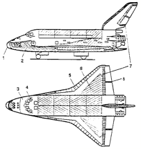
The lower surface and the most part of BURAN airframe lateral surface in the areas with maximum temperatures of aerodynamic heating 700…1250°C is protected by a reusable thermal protection in the form of ceramic tiles of silica fibers having white or black external erosion resistant coating (Figure 1).
|
|
Figure 1. Thermal protection elements of BURAN |
In the less heated areas for temperatures up to 350…370°C the flexible thermal protection made of fibrous organic materials is used.
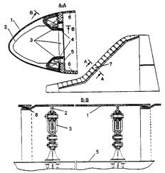
Such heat-resistant structure elements as nose fairing and sections of wings leading edges made of the carbon-carbon material with limiting exploitation temperatures up to 1650°C are related to the number of the most responsible components of BURAN thermal protection system. In spite of total similarity of BURAN with Space Shuttle orbiter a lot of its construction elements have many essential differences. For example, the main peculiarity of wing leading edge feature consist in sequential scheme of the sections mounting (Figure 2) that increases its reliability and reduces the number of carbon-carbon elements.
|
|
Figure 2. Wing leading edge construction |
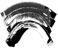
Illuminators of the crew cabin withstanding heating up to 750°C also can be considered as the elements of the thermal protection of multifunction assignment. Besides the heat-resistant screens from metallic honeycomb panels with limiting exploitation temperatures up to 400-700°C (Figure 3), different heat-resistant seals and also panels of the ablative thermal protection for inter elevon gap with heat resistance up to 1800°C are concerned to the elements of BURAN orbiter thermal protection system.
The responsibility for creation of the airframe and the number of systems of the BURAN orbiter including the thermal protection system was assigned on NPO MOLNIYA that alongside with fulfillment of the main volume of computational and design works executed general coordination of joint activity of institutes and organizations participating in the given project.
|
|
Figure 3. Heat resistant screens of metallic honeycomb panels |
The unique complexity of BURAN and the deadlines of its creation have demanded a broad paralleling of all the activities. Practically at the same time new materials were developed and different constructions from these materials were designed, the experimental researches were conducted and new test complexes were build. The objects of tests were also developed and they were presented as by geometrically similar BURAN models as by and full-scale fragments of its construction equipped with the necessary measurement means.
In the conditions when it was expected to receive the significant part of the experimental information required for checking of BURAN construction only at the completing stage of the work, the role of methods of computational simulation became practically dominating. To the number of main problems of BURAN thermal protection maintenance that were solved with the use of computational methods the following ones are related:
- definition of external heat fluxes at all stages of the flight and calculation of thickness of high-temperature thermal insulation for each surface segment of the airframe ensuring protection of its skin and supporting construction elements from an overheating;
- calculation of temperature change during the flight of the most responsible structure components - nose fairing, wing leading edges, corresponding fastening elements, crew cabin windows, metal skin of the airframe and a lot of other its aggregates;
- elaboration of computationally justified recommendations for temperature decreasing of separate units or details by the increase of external thermal protection thickness or change of construction parameters of the considered elements when the available materials do not withstand the operational heating;
- estimation of consequences of air plasma penetration inside of the airframe through possible defects in the skin and sealing elements during BURAN descent from the orbit;
- computational forecast of the airframe condition in case of damage or loss of any of 38000 thermal protection tiles glued on its surface.
|
|
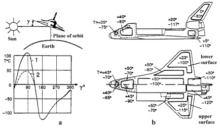
Figure 4. Temperatures distribution on the surface of BURAN at orbital flight stage |
The conditions of the thermal protection and BURAN construction operation can be divided into three groups appropriate to the main stages of the flight - joint flight with the ENERGIYA launcher, orbital flight and autonomous reentry flight at gliding descent in the atmosphere. For the injection stage the main factors of action on thermal heat protection system are the following: the vibration-acoustic loads, air dynamic pressure and non-stationary loads from shock waves that are the most essential in zones of attachment units of BURAN with the central stage of the launcher.
The additional factor promoting the increase of inertial loads on elements of the thermal protection system can be the increase of their weight due to moisture absorption under unfavorable weather conditions.
The aerodynamic heating on launch stage is rather small and is not decisive for the selection of the thermal protection. Only in the bottom part of BURAN the thermal protection of the base screen and number of other elements is selected pursuant to the levels of radiation heating from the jets of the launcher engines at a stage of joint flight.
In the orbital flight the elements of BURAN thermal protection in shadow zones can be cooled up to temperatures about –120°C or be heated up to +110°C under direct solar radiation (Figure 4,a). The minimum levels of the temperatures of the carrying structure elements also can reach –120°C and the most permissible heating of the metal skin of the airframe during the orbital flight is limited to +50°C on a technical requirement in order to more rational use of heat accumulating ability of the construction and by that to keep at an acceptable level of thermal protection weight, (Figure 4,b).
The practical fulfillment of this requirement for lateral and upper surfaces of the airframe is provided with the use of white color external coatings with low value of the solar absorption ratio to the emissivity (As/ε ≤ 0,4). For the lower surface of the airframe where more heat-resistant thermal protection with external coating of black color having the ratio As/ε ≈ 1 is used, the time constraint of its continuous orientation on the Sun (no more than 6 hours) is established.
Thermal protection of the BURAN experiences maximum thermal loads during the gliding descent in the atmosphere. The parameters of aerodynamic heating have essential spatial non-uniformity and are changed with time. And the maximum levels of surface temperatures are essentially defined by such physical properties of the surface coating of thermal protection as catalycity and emissivity. The temperatures levels of thin-walled noses of the fuselage and the wing leading edges essentially depend also on intensity of internal processes of radiation heat exchange. The maximum temperature values of heat-protected structure elements made of aluminum alloys at the moment of landing should not exceed +160°C at initial temperature before de-orbiting +50°C.
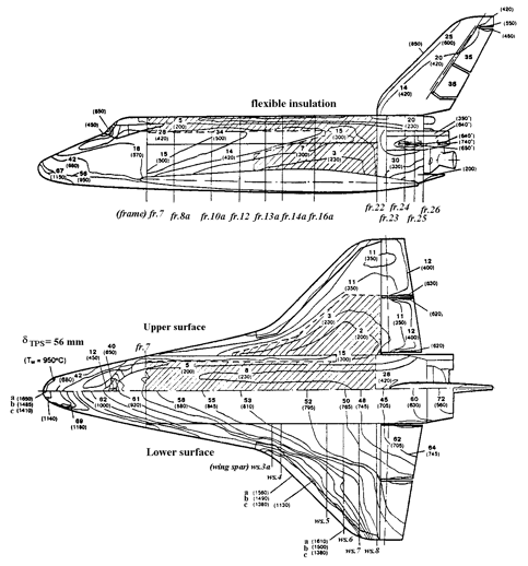
In Figure 5 the thermal protection thickness computational values ensuring in the landing moment temperature value of the metal skin of the airframe from D-16T aluminum alloy not higher 160°C are given. The levels of external heating for the standard design trajectory of descent, introduced by isolines of maximum temperatures on the surface of BURAN are obtained on the base of calculations, numerous tests of the scaled models in wind tunnels of TsAGI, TsNIIMACH and flight tests of thermal protection elements on BOR-4 flying model. The temperatures of the fuselage and the wing leading edges noses of carbon-carbon material for ‘a’ and ‘b’ variants (Figure 5) are calculated in view of physic and chemical processes in the shock layer and the catalytic properties of the surface but not taking into account internal reradiation and heat conduction processes (Kw = ∞ for ‘a’ variant and Kw = 3m/s for ‘b’ variant). The ‘c’ variant corresponds to Kw = 3 m/s and is calculated in view of processes internal re-radiation and heat conduction. The values of temperatures marked by (*) concern to the injection stage.
Actual thickness of the thermal protection is selected in view of the additional requirements to the smoothness of the external surface and other technological limitations. That is why they can a little differ from theoretical ones usually in the large party.
Computational Methods for Analysis of the BURAN Thermal Regimes
During BURAN orbiter creation for the first time at the industrial level the computational analysis of thermal regimes practically of its every structural member was made and the total expenses of the calculation time have reached tens thousand hours on powerful computers. The developed thermal mathematical models and algorithms have passed repeated check by comparison of the obtained results with the data of other authors and with the results of special laboratory and flight experiments. It allowed with sufficient confidence to forecast BURAN behavior not only at normal flight stages but also in conditions of abnormal situations.
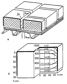
The comparative analysis of materials and computational substantiation of necessary thickness of BURAN thermal protection were conducted with the use of several types of mathematical models. Thus were taken into account the external conditions of heating, processes of radiation and convective heat exchange inside of airframe, heat exchange in the gaps between TPS tiles, real architecture of the load-carrying structure, dependence of thermal-physical characteristics on temperature and pressure and also a number of other factors. In Fig.6 one of the schemes for calculation of thermal protection and some obtained results are shown. The influence of the gaps between the tiles is easily seen. These gaps as a rule reduce efficiency of thermal protection and consequently should be carefully inspected at all the stages of the gluing, acceptance tests and exploitation. During computational researches the extremely important role of radiation heat exchange in internal cavities of the airframe construction was detected.
|
|
Figure 5. The theoretical scheme of TPS thickness for designed maximum temperatures on the BURAN external surface |
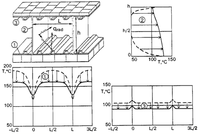
The purposeful account of these processes when developing BURAN orbiter allowed to reduce the required thickness of the thermal protection and to give the forecast of essential reduction of unfavorable temperature gradients. The intensity of heat transfer by radiation from more heated zones of the construction to less heated ones in some cases predominates above processes of heat conductivity. It is well seen in Figure7 by comparison of thermal calculation results obtained for a fragment of the wing in view of radiation heat exchange and without it.
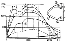
For the most heated elements of BURAN construction such as nose fairing and leading edges of the wings the account of radiation heat exchange allowed to reduce design levels of maximum temperatures on 100…150°C. In Figure 8 the temperatures change on time in characteristic points of carbon-carbon section of the wing leading edge for one of computational versions is shown. Due to radiation heat transfer the temperature difference between the lower and upper parts of the section decreases from 1150°C down to 500°C and at the same time in the area of maximum heating the temperature decreases approximately on 120…150°C.
|
|
Figure 6. The scheme and the results of BURAN thermal protection calculation |
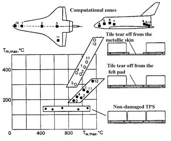
One of the most serious problems of the thermal protection use is represented by possible loss of thermal protection elements. The conducted calculation-experimental researches allowed before the first flight of BURAN to give the justified forecast, that the damage or tear off of any one thermal protection tile in most cases will not cause melting of the airframe skin i.e. the origin of the crash. It is illustrated in the generalized kind on Figure 9 where for several areas of BURAN orbiter depending on the maximum temperature for the non-damaged thermal protection external surface Tw, max , the computational maximum temperatures of the airframe metallic skin are given as for the normal condition of the thermal protection as in case of loss of one element of the thermal protection system. Two versions in the latter case are considered: tile tear off with preservation on the metal skin of the felt substrate (most probable case) and tile tear off together with the felt substrate.
It is seen that at preservation of the felt substrate the skin melting temperature (about 500°C) is not reached in all range of the external heating levels of 270…1250°C and at the tile tear off together with the felt the integrity of the skin can be damaged only in the areas adjacent to carbon-carbon fairing.
At BURAN launch in winter conditions and bad weather some TPS tiles were damaged by the ice dropped from launching constructions, from the launcher and the orbiter itself. Several tiles were torn off completely. However post-flight inspection has shown that the metal skin melting did not occur in these places except for one area where due to seal defect in the joint of thermal protection with section of the wing leading edge a capability of intensive of air plasma flow inside of the leading edge cavity was realized. These results of the orbiter first flight completely confirmed the preliminary computational forecasts on the degree of reliability of its thermal protection.
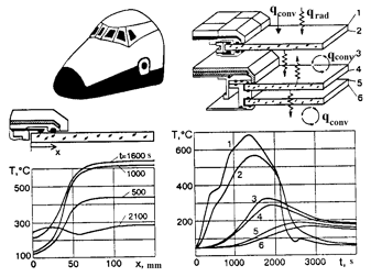
The developed calculation methods of thermal regimes of BURAN windows allowed at the stage of designing to analyze in details possible gradients of temperatures and levels of glasses heating (Figure 10) and by that to increase reliability of windows construction and also to reduce costs of their experimental development.
Experimental Methods of BURAN Thermal Protection Development
The experimental methods in a combination with computational ones were widely used at all the stages of creation and experimental development of BURAN. In ground conditions thermal protection and hot structure elements were conducted mainly on gasdynamic facilities and stands of radiation heating. In flight conditions the large experimental program was made by airplanes flying laboratories and by space unmanned vehicles BOR-4 and BOR-5.
From the gasdynamic type facilities the most important results were obtained on induction and electric arc plasmatrons.
|
|
Figure 7. Thermal calculation of a fragment of the BURAN wing |
|
|
Figure 8. Temperature regimes of the wing leading edge at the descent |
One of the main advantages of the high-frequency plasmatrons with induction type of working gas heating is the high purity of a gas flow that allows to simulate chemical interaction of air plasma with materials and to investigate extremely important problems of catalytic activity of the external surfaces of thermal protection and constructional elements at their interaction with flows of dissociated air imitating real flight conditions.
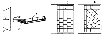
Electric arc plasmatrons are rather old kind of the test equipment. Most productively they were used at the experimental development and qualification tests of ablative thermal protection materials. The field of this equipment application for tests of the reusable thermal protection is also wide enough and covers thermal and gasdynamic tests at which it is possible not to take into account influence of electrodes erosion products contained in a plasma flow. The schemes of tests of the thermal protection panels with different orientation of the tiles in the electric arc plasmatron (U-15T-1 TSNIIMACH) are shown in Figure 11.
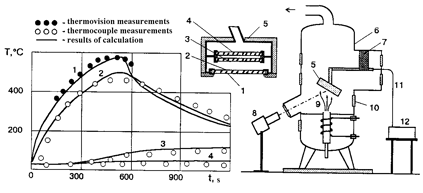
In Figure 12 the scheme and the results of the tests of the full-scale window of BURAN access hatch in induction plasmatron VGU-3-200 (Institute of problems in mechanics of the Russian Academy of sciences) is shown. Maximum diameter of the tested object was about 500 mm. The temperature of the external surface of the window was inspected by infrared system AGA-780 and the temperature conditions of the internal elements was registered via thermocouples indications with the help of the multi channel data acquisition system ORION-3500.
|
|
Figure 9. Maximum temperature values of the airframe skin after loss of one thermal protection tile |
|
|
Figure 10. Computational modeling of radiation–convection heat exchange processes in multi-glass cabin windows |
The stands of radiation heating are the most economic equipment for research of the construction and thermal protection elements temperature condition practically in all range of the BURAN operational temperatures i.e. from - 150°C up to 1600°C. Thus for orbital conditions both visible and infrared band of the spectrum are used while for modeling of high-temperature heating the heaters with infrared spectrum of radiation are mainly used.
|
|
Figure 11. Experimental study of the tiled thermal protection in electric arc plasmatron: |
1 –nozzle of plasmatron; 2 - cooled holder of the tested object; 3 - tested object; 4,5 - TPS panels with different orientation of thermal protection tiles
|
|
Figure 12. Test of the BURAN access hatch window in induction plasmatron VGU-3-200: |
1 … 4 – points of the temperature measurement; 5 – tested object; 6 - low-pressure chamber; 7 - coordinate device; 8 – thermovision system AGA-780; 9 – plasma flow; 10 - window; 11 – thermocouples output; 12 - multi channel measuring system ORION-3500
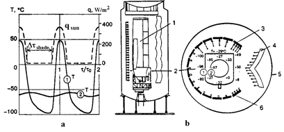
|
|
Figure 13. Thermal-vacuum test of the BURAN fragments in conditions of orbital flight simulation: |
a - calculated thermal regime; b - scheme of the tests; 1 - tested object; 2 - computational cross-section; 3 - simulator of the Earth radiation; 4 - simulator of the solar radiation; 5 - vacuum chamber; 6 - cryogenic screens
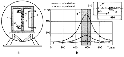
|
|
Figure 14. Experimental study of the thermal protection on the radiation heating stand KTVU-40G: |
a – the scheme of the experiment; b - temperature of the metal skin of the panel under thermal protection; 1 - vacuum chamber; 2 - test module ‘black box’ with the internal thermal insulation; 3 - mounting points o f the tested object; 4 – the tested panel of the construction with thermal protection; 5 - area of damages imitation; 6 - radiation heater; 7 - thermocouple on the metal skin of the panel
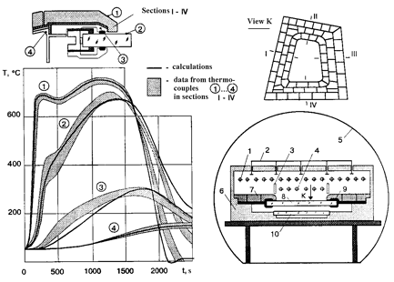
|
|
Figure 15. Tests of the BURAN frontal window on the TPI-9 stand: |
1 - main heater; 2 - jet cooling system; 3 - separating screen; 4 - additional heater; 5 - vacuum chamber; 6 - thermal insulation of the stand; 7 - standard thermal protection; 8 - external glass of the window; 9 - the edging of the glass; 10 - fragment of the cabin glass

|
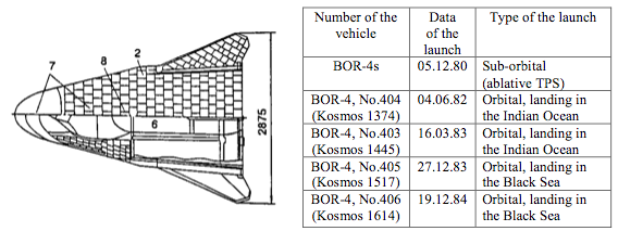
|
|
Figure 16. Experimental researches of BURAN thermal protection on flying vehicles of BOR-4 series: |
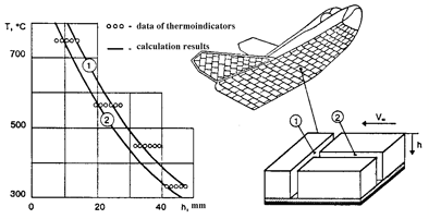
1 - nose fairing from GRAVIMOL material with M-46 antioxidation coating; 2 – thermal protection tiles of TZMK-10 and TZMK-25 material with black coating EVCH-4M1Y3; 3 – thermal protection tiles of TZMK-10 material with white coating EVS-4; 4 - flexible thermal protection ATM-19 with white coating UF-11; 5 - calorimetric sensors; 6 – thermopaints on the upper and the lower surfaces; 7 - thermocouple on the nose fairing, TPS tiles, airframe; 8 thermoindicators in the gaps between tiles
|
|
Figure 17. Measurement of maximum temperatures in the gaps between thermal protections tiles of BOR-4 flying vehicle with the help of thermopaints: |
The principal scheme of the fuselage middle part tests on KVI test facility of NIIchimmach is shown in Figure 13. External thermal loads were set on the base of results of numerical calculations of direct radiation intensity from the Sun and the Earth and also of the reflected fluxes and own radiation of BURAN.
|
|
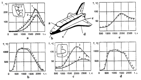
Figure 18. Comparison of the flight data with the results of the BURAN orbiter construction computational forecast: |
a - internal surfaces of the outside glasses of frontal (1) and middle (2) windows; b - nose fairing in the area of the maximum aerodynamic heating; c - skin of the lower (3) and upper (4) surfaces of wing glove in the area of the frame 10; d - section 9 of the wing leading edge in the area of the maximum aerodynamic heating; e - the skin of the lower fuselage surface in the area of the frame 17.
One of the largest facilities for high-temperature infrared heating is the TPVK-1 stand (TsAGI) on which there was tested such a large fragment of BURAN o as 1/3 part of the fuselage with one wing. Smaller-sized objects were tested on large number of other stands such as KTVU-40G (NPO MOLNIYA) and TPI-9 (SibNIA) stands.
These facilities are well automated and allow with high accuracy to reproduce dynamics of the heating parameters and external pressure variation according to the parameters of real flight. That is why they are very convenient for realization of multi-cycle tests.
In Figure 14 the scheme of experiment on KTVU-40G stand for simulation of consequences of one thermal protection tile loss is shown and the obtained data in comparison with computational results are presented. In Fig. 15 the scheme of the frontal window tests on TPI-9 (SibNIA) stand and the comparison of computational results with experimental data are shown.
The large-scale flying models of BOR-4 series (Figure 16) have ensured the extremely important experimental information on behavior of the reusable thermal protection elements in conditions of the gliding flight in the atmosphere on the trajectory close to the BURAN orbiter descent trajectory.
The maximum levels of heating were updated and the number of computational models of heat exchange was corrected. The test of all the main components of the BURAN thermal protection including carbon-carbon material for the most heated areas of the fuselage nose and wing edges, heat-resistant thermal protection tiles with black coating for the lower surface and with white color for the lateral area of the airframe and also flexible thermal protection for an area of the upper surface was conducted. The capability to install the large number of measurement means allowed to examine thermal regimes in the interested areas of construction and if necessary to make corrective amendments to the measurement methods before the next restart of the vehicle.
In Figure 17 the comparison of the computational data on the maximum temperatures in the gaps between TPS tiles with corresponding results of flight measurements with the help of thermal paints on BOR-4 vehicle are shown.
The Results of the BURAN First Flight
In Figure 18 the comparison of the computational data and measurements results of thermal regimes for the most responsible structure items of BURAN obtained during its real flight are shown. Somewhat lower thermal loads corresponds to the trajectory of this flight than for standard design conditions of the descent. That is why the temperatures measured in the flight were below maximum permissible ones. At the same time the good coincidence of the real data with the appropriate predicted values allows with definite confidence to design new flight vehicles on the base of the computational data on their thermal regimes. The experimental check is better to conduct only on the final stages of the work and only for the most responsible elements that doubtlessly will allow reduction the cost of new development.
Conducted at present in NPO MOLNIYA design researches on creation of MAKS aerospace transportation system are substantially based on the results of work under ENERGIYA-BURAN system. The use of the materials with improved properties and application of the improved methods of the computational design allows on preliminary estimations to achieve lowering specific weight of the thermal protection on a unit of a surface on 25-35% in comparison with the similar parameters for BURAN orbiter.
Conclusion
On the base of the presented information it is possible to make the following conclusions:
- the developed methods and algorithms for thermal condition simulation of spatial load-carrying structures with thermal protection provide complex problem solving of the thermal design of complicated aerospace systems;
- during design and experimental development of the BURAN orbiter the unique practical experience is gained of computational analysis at an industrial level of the thermal regimes of all of its main structural elements;
- the good coincidence of the computational and experimental data obtained both during ground experimental development and the real flight confirms reliability of the created methods;
- offered methods of the computational and experimental simulation of the thermal regimes were successfully tested for the number of Russian and European space vehicles and further can be widely used when creating new generation launching systems such as MAKS or similar one.
References
1. Timoshenko V.P. The Computer Program ‘Thermal Protection’ – Calculation of Temperature Distribution and Precession of Multi-layer Thermal Protection Coatings with Account of Thermal Degradation of Ablative Materials and Non-Stationary Filtration of the Gas. – TsNIIMASH, GONTI-1, OFAP No. 0542P, 1980. – 104 p.
2. Timoshenko V.P., Shiparev V.A. Calculation of the Temperature Fields in Flight Vehicles Construction with the Use of Thermal Models on the Graphs // Gagarin’s Scientific Readings on an Astronautics and Aviation, 1981. Moscow, NAUKA, 1983. – 147-148 pp.
3. Zemlyansky B.A., Lunev V.V., Timoshenko V.P. and oth. Some Problems of Heat Exchange of Hypersonic Flight Vehicles of Gliding Descent // Works of NPO MOLNIYA, 1985, No.1. - 34-61 pp.
4. Timoshenko V.P., Patrichnaya M.P. Temperature Regimes of the BURAN Thermal Protection in View of Radiation Heat Exchange in the Gaps Between TPS Tiles// Works of NPO MOLNIYA, 1985, No. 2. - 70-78 pp.
5. Volkova S.N., Zemlyansky B.A., Timoshenko V.P. Heat Exchange and Temperature Regimes of the BURAN Wing Leading Edge // Works of NPO MOLNIYA, 1985, No. 2. - 78-87 pp.
6. Timoshenko V.P., Trenev M.G. The Method of Thermal Regimes Calculation of Multi-layer Semi-Transparent Materials // Scientific notes of TsAGI, 1986, book 17, No. 2. - 83-93 pp.
7. Timoshenko V.P., Trenev M.G., Patrichnaya M.P. The Computational Simulation of Complex Heat Exchange in Spatial Structures of High-Temperature Isolation Elements // IFTPE, AN LitSSR, Works of the 6-th All-Union technological conference, Kaunas, 1987. - 127-128 pp.
8. Omelchanko K.G., Timoshenko V.P., Trenev M.G. and oth. Methods of Calculation of Thermal Protection Coatings and Temperature Regimes of the Elements of Vehicles Operating in Conditions of Intensive Heating. TsNIIMACH, GONTI-1, 1989. – 131p.
9. Timoshenko V.P. The Matrix-Zone Method of Radiation Heat Exchange Calculation Between Elements of Complex Constructions // Gagarin’s Scientific Readings on Astronautics and Aviation, 1990-1991 years. Moscow, NAUKA publishing house, 1991. – 139 p.
10. Timoshenko V.P., Yakushin M.I., Patrichnaya M.P. Thermo Vision Control of the hermal Regimes at the Tests of Construction and Thermal Protection Elements of BURAN Orbiter in Induction High-Frequency Plasmatron VGU-3-200 // Engineering of Air Fleet, 1993. No. 4-6, - 72-74 pp.
11. Timoshenko V.P. The Use of Heat Exchange Computational and Experimental Simulation Methods at Creation of BURAN Orbiter. // Problems of Air and Space Engineering, 1994,No. 2. - 26-30 pp.
12. Voinov L.P., Zalogin G.N., Lunev V.V., Timoshenko V.P. The Comparative Analysis of the Laboratory and Flight Data about the Materials Catalycity of BOR and BURAN Flying Vehicles Thermal Protection. // Astronautics and Rocket Manufacturing, 1994, No. 2. - 51-57 pp.
13. Timoshenko V.P. BURAN’s Main Thermal Protection Components // Proceedings of the First ESA/ESTEC Workshop on Thermal Protection Systems, Noordwijk, Netherlands, ESA-WPP-053, pp.40-57, 1993.
14. Tarasov A., Timoshenko V., Skorodelov V. Use of Advanced High Strength Materials for Design of BURAN and MAKS Structures with Minimal Weight // Proceedings of the International Symposium on Advanced Materials for Lightweight Structures, Noordwijk, Netherlands, ESA-WPP-070, pp.25-38, 1994.
15. Yeryomina A., Timoshenko V., Zhestkov B. Terentieva V. Thermal-Resistant Antioxidation Coatings for Composite and Metallic Elements of Aerospace Vehicles // Proceedings of the 2nd European Workshop on Thermal Protection Systems and 3rd European Workshop on High Temperature Materials, Stuttgart, 1995.
16. Shirokikh D., Timoshenko V. Development and Application of Honeycomb Hot Structures // Proceedings of the 2nd European Workshop on Thermal Protection Systems and 3rd European Workshop on High Temperature Materials, Stuttgart, 1995.