

- Documentation
- Table of contents
- AKC
- Introduction
- Airframe Creation
- Technological Problems
- Experimental plant
- Building plant
- Conf. Development
- Aerodynamic Designing
- Algorithms of control
- Guidance & control
- Stand for training
- Training center
- Horizontal flight tests
- Crew on board
- Auto Landing complex
- Structure
- Payload bay
- Metallic material
- Non metallic material
- Non metallic material
- Cabin assembly
- Thermal designing
- Thermal protection
- Heat protection
- Quartz fibre
- Computer designing
- Gas's dynamic
- Strength
- Basic direction
- Tech. preparation
- Technical diagnostics
- Methods & means
- Radio nav. support
- Information & controls
- Control of onboard equ.
- Electric power dist.
- Electromagnetic
- Antennas installation
- Auxiliary power unit
- Hydraulic system
- Cabin
- Safety
- Air transportation
- Automatic landing
- Exp. working out
- Return to space
- SPIRAL
- Analysis of concept
- Horizontal take-off
- BOR-4 & BOR-5
- MAKS multipurpose
- MAKS-D
- Thermal design
- Gas & thermal design
- Wing deflection
- Flight performance
- Maks structure
- Metal materials
- Advanced non metallic
- Information provision
- Onboard starting comp.
- Onboard control comp.
- Control organization
- Aerospace systems
- Economic investigations
- Triplane aircraft
- Technical inventions
- Scientific potential
- Triumph and tragedy
- Birds of a Feather?
- TsAGI wind tunnel
- Bibliography
| -The Mriya is destroyed. |
| -Shipping of Buran-KS to Sotchi. |
| -Antonov is no more. |
| -Buran is now a museum. |
| -New pictures of the blogger Ralph Mirebs. |
BURAN Orbital
Spaceship Airframe
Creation
Thermal Designing of the BURAN Orbital Spaceship
Voinov L.P.
The thermal and force effects on the Orbital Spaceship in space flight and at descent from the orbit are considered. It is presented distribution of temperatures and pressure on a surface and on this basis it is chosen scheme and structure of the Heat Protection System. Method of definition of thermal protection thickness for the Orbital Spaceship is stated.
Non recessed reusable thermal protection system (TPS) is used in BURAN orbiter. This TPS is of radiation type and practically all the convective heat flux appearing at descent from the orbit radiates into the atmosphere.
Main structural elements of the orbiter TPS system are the following: thermal protection quartz tiles, segments of the wing leading edges, fuselage and tail fins, the wings tips, elements of elevons heat protection and also the windows of the cabins.
TPS of the BURAN orbiter provides minimal weight, smoothness and preservation of the airfoils shapes, and while in service – the forecasting of the aerodynamic, weight and centering characteristics.
The thermal protection operates under action of extreme space environment with temperature 4К in the shadow and the maximum solar radiation flux not absorbed by the atmosphere (q ~ 1,4 kW/m2) that results in TPS surface temperature on the orbit accordingly -150°С and +150°С.
At descent from the orbit TPS is streamlined by the high-temperature flow of rarefied and dissociated air with temperature in the equilibrium condition 6000К (in a gas behind the shock wave 28000К). Within 15-20 minutes on the TPS surface on the nose blunting of the wing and the fuselage it is formed the equilibrium temperature exceeding the melting temperature of carbon steels and on the lower surface of wing and fuselage - the melting temperature of gray pig iron and copper.
During the start, injection and descent from the orbit on the TPS act the large shock-wave loads exotic for the airplanes. At start of liquid rocket engine (± 0,15 kgf/cm2) and acoustic loads (164 dB) created by rocket engines hot jets of a total thrust about 4000 tons.
The large acoustic loads (of 162 dB) with a spectrum shifted to the area of low frequencies are formed at streamlining on transonic flight regimes of rounded noses of the wing and the fuselage with large radiuses of bluntness and great intensity shock waves interacted with the surface and with each other.
The orbiter TPS mainly determines aerodynamic layout and design concept.
On the aerodynamic layout the BURAN orbiter is a wide-fuselage strongly blunt-shaped classical ‘tailless aircraft’ with delta-wing of double sweep in the plan. The leading edges are rounded in unusually large radiuses and back ones are made as flat end face of the double thickness TPS. The lower border of the wing and fuselage blunting radiuses values is determined by permissible temperature (1650°С) of erosion resistant coating of carbon-carbon constructional material from which the carbon noses and some fragments of the construction are made.
In order to decrease the carbon noses temperature on 100-150°С by means of heat flux re-radiation from the lower surface of blunting to the upper less heated one the bluntings are made hollow with the maximum radiation transparency.
The arrangement of the first behind carbon TPS quartz tiles row representing the composition of continuous structures from ultra thin fiber with density 150 kg/м3 is determined by permissible temperature 1250°С of reusable use on 100 flights (on one test flight without change of the shape the temperature 1400°С with the subsequent replacement is supposed).
The nose blunting of each wing cantilever is broken on 18 sections (in cross-section is of horseshoe shape).
For compensation of the temperature expansions and the decrease of aerodynamic loads during the flight in dense atmospheric layers, on the upper surface of each section controllable gaps are stipulated which together with a drainage aperture in the end face of last section provide predictable pressure inside the sections and significant decrease of flexural stresses in the ‘horseshoe’.
The position of cold metal forward walls of the wing and the fuselage covered by quartz TPS and closing hollow carbon sections is also determined by permissible temperature of TPS tiles (1250°С). Erosion resistant coating on the forward wall of the wing and the fuselage is absent.
Quartz lightweight TPS protects from high-temperature air plasma at de-orbiting stage the primary structure of the orbiter airframe made from aluminum alloy and carbon plastic which temperature at the moment of landing should not exceed +160°С. Quartz TPS is the ideal heat-insulating material as it has enough low heat conductivity in space and at de-orbiting. It is produced from ultra thin, 1.5-2.0 microns diameter fiber and amorphous crystal of high cleanliness (98-99% SiO2) with the minimal alkaline metals oxides contents (Na, Ka, Ca) which impurity reduce the melting temperature a quartz fiber and promote its early crystallization. The thermal conductivity of the TPS strongly depends on the temperature and pressure (see table).

|
|
Relation of TPS thermal conductivity coefficient from pressure and temperature, W/(m °) |
The presented values of heat conductivity are given by the developer of the TPS material in the technical project of the customer.
In each point of the airframe surface the TPS thickness is defined depending on the effective thickness of the construction material, distribution of temperatures and pressure along the airfoil and with time of the descent trajectory. That is why the TPS actively influences on the airframe structural- loading scheme. It determines expediency of application of the combined construction from the condition of the minimal weight and the place of horseshoe hollow carbon blunting docking of the hot construction with moderately heated up (up to 160°С) metal airframe construction.
The TPS should be erosion resistant against the sand, rain and hailstone, hydrophobic and non-hygroscopic one. All this is provided by erosion resistant impermeable surface glass-like coating (black and white) of 0,3 mm thickness fused into lightweight continuous structure of the welded ultra thin fiber and by its hydrophobic impregnation with expendable coating of the external surface by burned out lacquer. The TPS should be radio transparent in the broad band of used radio frequencies. For maintenance of maximum radiation of the convective heat flux at de-orbiting the TPS external surface should have the integral emissivity ε = 0.8-0.92 - black coating (0.92 at the initial stage of operation and 0,8 after 100 flight cycles).
For overheating prevention of the construction side directed to the Sun (+50°С) the TPS coating (white) has absorptivity of the solar spectrum As < 0.32 i.e. As/ε < 0.4.
TPS coating is catalytically neutral with the constant of speed of the catalytic recombination on oxygen and nitrogen Кw O,N<2 m/s at which the temperature on the nose blunting of the fuselage can be reduced on 300-400°С and on the lower surface of the fuselage on 100°С.
The BURAN orbiter TPS should withstand all kinds of aircraft loads on operation phases regulated by the general technical requirements of Military Air Forces for heavy wide-fuselage airplanes and also thermal shocks created by the shock waves acting on the airfoil, for example of a strong shock wave outgoing from the fuselage nose blunting and crossing both cantilevers of the wing at Mach number M=15…23.
For thermal stability maintenance at a thermal shock it is necessary to aim to the minimal value of thermal expansion coefficient of TPS material.
The only one natural material capable to maintain the thermal shock up to temperature 1250-1400°С with the subsequent instant cooling and having the minimal value of thermal expansion coefficient α= 0.5·10-61/grad (amorphous quartz of high purity).
The BURAN TPS successfully withstand resource tests on plasmatrons during 100 cycles, in real conditions of 4 space flights on BOR-4 flying models and in the first flight of BURAN.
The essential differences in temperature deformations of rigid TPS tiles and elastic airframe structure under aerogasdynamic and inertial forces action required TPS cutting on separate square tiles of 150х150 mm size of various thickness on the location. For temperature deformations compensation the computational inter tile gap should be not less than 0,8 mm for a 150×150-mm size tile at temperature +15°С at absence of load.
The decreasing of the gap at the given size of the tiles will cause the tile chip on orbit at the negative temperature -150°С. The maximum inter tile gap is determined by the tolerances on the tile manufacturing and should not exceed 1.4 mm = (0.8+2х0.3) mm. The permissible value of inter tile gaps was investigated in wind tunnel tests on the models and was checked up in the flights on BOR-4 flying models. Thus appreciable input of the convective heat on the chosen inter tile gap was not revealed and large input of heat was measured only in gradient (on pressure profile) zones where inter tile gaps are filled by loose-fiber silica composition. The TPS tile is glued to the airframe skin through the felt pad of 4 mm thickness for compensation of elastic deformation of the airframe skin under the tile.
Inter tile gaps should be placed along lines of constant pressure or on normals to streamlines in the boundary layer that reduces convective heat input and promotes shift of the area of laminar-turbulent transition into the area of the flight trajectory of smaller altitudes and Mach numbers.
The increase of laminar flow regime duration when de-orbiting provides decreasing of turbulent heat entry into BURAN TPS and reduces the skin heating. The arrangement of the gaps sequence of several tiles along the streamline (the “glazed” stacking) provides distribution of the instability disturbances downstream that provokes early laminar-turbulent transition. Inter-tile gaps arrangement on the normal to the streamline (the ‘brick’ stacking) can a little bit increase heating of the blocks corners in area of Т-type gaps but it, however, provides flow blocking in the inter-tile gap along the streamline within the limits of one tile.
The experimental researches on the models confirmed the advantages of the ‘brick’ stacking in comparison with the ‘glazed’ one.
Let's consider relation of pressure profile and temperature on time of de-orbiting and their influence on thickness of the BURAN orbiter TPS.
The main technical documents determining the shape of the orbiter are the schemes of temperature distribution and TPS thickness on airfoils of the plane.
The development of the temperature scheme always is preceded by the analysis of the pressure profile and streamlines on the surface of the plane.
For calculation of TPS thickness distribution it is necessary on the base of the analysis of the computational and experimental data to set the pressure profile on the airfoil and its change on the flight trajectory in connection with relation of TPS thermal conductivity from pressure and temperature.
The pressure profile should be for sure taken into account at heat fluxes calculation as it determines the direction of the streamlines in the boundary layer and in the exponential function is connected with heat transfer coefficient α = KР0.5…0.8, where k is the coefficient of proportionality.
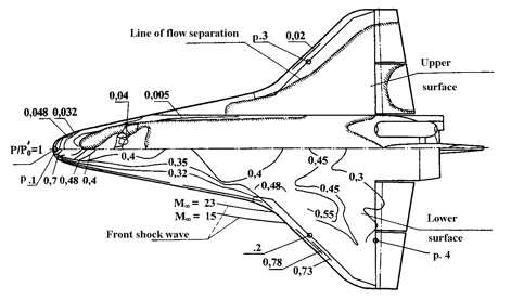
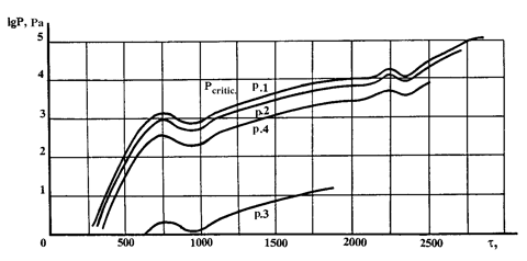
The orbiter surface pressure and its time change during the decent stage are illustrated in Figures 1, 2.
The experimental determination of the heat fluxes during de-orbiting represents the task of extreme complexity and has got the decisive meaning on the orbiter airframe creation. The large place in its solution takes modeling gasdynamic experiment in various wind tunnels for which in the beginning of the 80’s the number of geometrically similar models of BURAN orbiter and its fragments - 97 thermal, 27 gasdynamic, 16 acoustic - was created. The new methods of thermal and thermo-vacuum tests were developed and the researches of heat exchange in real flight conditions on BOR-4 and BOR-5 flying models with the use of the newest means of thermal diagnostics were carried out.
The researches of heat exchange on the models were conducted on the experimental base of TsAGI and TsNIIMASH.
The important element of temperature distribution refinement on the orbiter surface were the researches in NPO MOLNIYA of laminar-turbulent transition in the boundary made together with MFTI and ITPM SO AN. For the first time in our country the necessary programs of laminar-turbulent transition calculation were created and for the first time in the world the effective theoretical methods of instability amplitudes calculation exited in the boundary layer were developed that allowed purposefully to decide the problem of the boundary-layer flow control and to analyze the expanding of unstable disturbances.
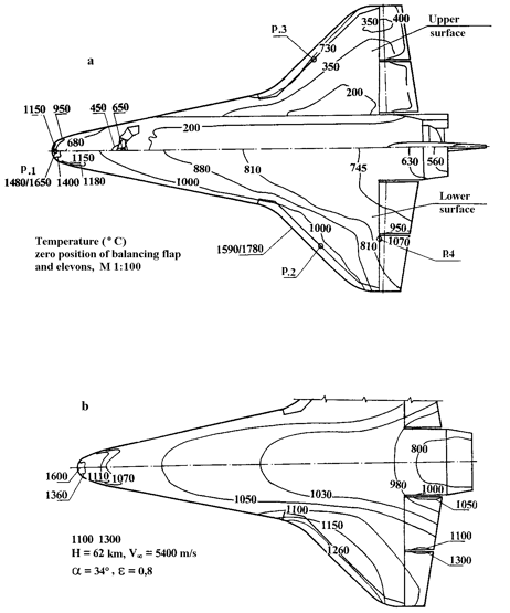
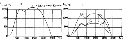
On the basis of the results of wind tunnel tests NPO MOLNIYA together with TsAGI and TsNIIMASH have composed the schemes of maximum temperatures distribution on adiabatic wall surface on laminar (Н = 71 km, V = 6770 m/s) and turbulent (Н = 62 km, V = 5400 m/s) modes (Figure 3) and in the characteristic points on the flight trajectory (Figure 4).
The equilibrium temperature of the adiabatic wall is set from the condition of equality of heat radiation on the surface with the integral emissivity ε=0.8 in ambient space to the convective heat flow from the catalytic active surface with the speed of recombination of the dissociated atoms of oxygen and nitrogen Кw O,N.→∞. The greatest catalytic influence is observed on the most heated nose of fuselage. On the leading edges of the wing the catalytic influence decreases because of the presence of the sliding component of the velocity vector of the external airflow and decrease of the intensity of the diagonal shock.
At moving off along the streamline from the leading edges the catalytic influence decreases. On the turbulent mode because of a rather low speed of the flight (V = 5400 m/s) where the turbulent maximum of temperatures is observed, the catalytic influence is insignificant.
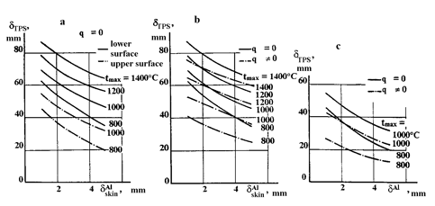
Having chosen ‘the trajectory for thermal calculations’ and having done the numerical calculations on non-stationary heating (at de-orbiting) of the primary structure skin covered by TPS with defined reference temperature of the skin tinitial = +50°С and final temperature at the moment of landing tlanding = +160°С we receive the relation of the TPS thickness to the given thickness of the skin (Figure 5).
From the analysis of Figure 5 it follows that the pressure strongly influences on the TPS thickness. Because of pressure difference the TPS temperature on the upper surface is much lower. At the same temperatures (800°С) and 1 mm thickness of the skin TPS on the upper surface of the plane is on 30% thinner only due to the pressure.
The TPS thickness also strongly depends on the temperature and the skin thickness. So, for example, at the equal pressure and the skin thickness δskin=3 mm on the lower surface of the fuselage, the TPS thickness near to the nose blunting is 65 mm and in the aft part - 45 mm i.e. it is 30% less only due to the temperature value. At thinning-down of the skin from 3mm to 2mm the TPS thickness increases by 5 mm i.e. on 15%.
On the base of existing scheme of the skin cutting with the use of relation of temperature change and pressure on time in each point of the BURAN airfoil, the theoretical scheme of TPS thickness was received that serves the main document for the issue of the TPS constructive scheme and for calculation of limit weights, design centering and inertial characteristics.
The theoretical scheme of thickness initially contains steps and waviness on the aerodynamic surface as the consequence of thickness ‘discontinuity of the airframe skin. For ‘smoothing’ of the aerodynamic shapes and limit weights preservation this scheme was undergo to careful design-theoretical study before the issuing of the constructive scheme of TPS cutting.
|
|
Figure 1. Distribution of dimensionless pressure on BURAN surface on the mode of maximum heat fluxes at Mach number M = 15-25 |
|
|
Figure 2. Pressure variation in characteristic points on the flight trajectory |
|
|
Figure 3. Distribution of the maximum temperatures on the BURAN orbiter surface |
a - on the laminar mode (with the account of catalycity and re-radiation / without the account...); b - on the turbulent mode
|
|
Figure 4. Distribution of the maximum temperatures of the adiabatic wall in the characteristic points of the wing and fuselage surface in view of the laminar-turbulent transition |
a - in the stagnation point of the nose blunting (p. 1); b - on the joint of the carbon nose with the tile (lower surface - p.2, upper surface - p.3) and on the joint of the elevon with the wing (p.4); the places of the points are shown in Fig. 3, а
|
|
Figure 5. Relation of the TPS tile thickness from the thickness of the skin and boundary conditions |
а - on the lower and upper surfaces without the account of re-radiation; b and c - accordingly on the lower and upper surfaces with the re-radiation account and without its account
For the issue of the specified basic design schemes there was necessary full gasdynamic calculation of the flow around the airplane on hypersonic speeds at real physic-chemical properties of the air desirably with the account of non-equilibrium processes and surface catalycity.
As the result were received spatial distribution of the shock waves, local velocities distribution on the aerodynamic surface, Mach numbers, dimensionless pressure, factors of friction and heat transfer, the streamlines, thickness of the boundary layer and its thickness of displacement, loss of the impulse and distance to a shock wave, .
On the base of these calculations the integral characteristics of friction forces, pressure and total loads on all the flight path stages (including the injection stage) were calculated.
The spatial calculations of streamlining were carried out on subsonic and especially on supersonic flight stages of M = 0.7-1.5 with the purposes of detection of unstable local shock waves position exited by the curvature of the surface and with the purpose of definition of their moving speeds for calculation of tearing off (pressing) forces acting on TPS tiles.
Transonic calculations allowed defining the boundary conditions at calculation of acoustics under the task of the areas differing by the frequent characteristics, intensity and place of acoustic loading.
The spectral characteristics of acoustic loading from the shock waves and from the flow separation areas is different. At the flow separation areas they are shifted into the area of lower frequencies, that it is more dangerous to the aircraft construction.
In more detail the features of gasdynamic designing are stated in the paper of Mr. Sokolov V.E., acoustic and shock wave loading are in the paper of Mr. Rosanov I.G. of the present book.
Conclusions
1. In the base of TPS scheme and construction development there was put the distribution of temperatures and pressure on the airfoil and on time (on the trajectory of descent).
2. When developing the temperatures distribution scheme on the nose of the fuselage and the wing it was taken into account the surface catalycity and on the aft part - laminar-turbulent transition that allowed to reduce the temperature on the trajectory of descent and to reduce the TPS weight.
3. When calculating the construction temperatures on the orbit and at descent it was taken into account re-radiation and spectral characteristics of special coatings which application reduced the orbiter heating.
4. For the tightening of laminar-turbulent transition and consequently decreasing the thermal effect on the orbiter construction TPS ‘brick’ type tiles stacking was applied.
5. The developed TPS satisfied all the requirements in view of extreme thermal and power effects in conditions of the orbiter functioning within the limits of the given resource.
6. The experience of BURAN orbiter TPS development can be used when designing aerospace transport systems.