

- Documentation
- Table of contents
- AKC
- Introduction
- Airframe Creation
- Technological Problems
- Experimental plant
- Building plant
- Conf. Development
- Aerodynamic Designing
- Algorithms of control
- Guidance & control
- Stand for training
- Training center
- Horizontal flight tests
- Crew on board
- Auto Landing complex
- Structure
- Payload bay
- Metallic material
- Non metallic material
- Non metallic material
- Cabin assembly
- Thermal designing
- Thermal protection
- Heat protection
- Quartz fibre
- Computer designing
- Gas's dynamic
- Strength
- Basic direction
- Tech. preparation
- Technical diagnostics
- Methods & means
- Radio nav. support
- Information & controls
- Control of onboard equ.
- Electric power dist.
- Electromagnetic
- Antennas installation
- Auxiliary power unit
- Hydraulic system
- Cabin
- Safety
- Air transportation
- Automatic landing
- Exp. working out
- Return to space
- SPIRAL
- Analysis of concept
- Horizontal take-off
- BOR-4 & BOR-5
- MAKS multipurpose
- MAKS-D
- Thermal design
- Gas & thermal design
- Wing deflection
- Flight performance
- Maks structure
- Metal materials
- Advanced non metallic
- Information provision
- Onboard starting comp.
- Onboard control comp.
- Control organization
- Aerospace systems
- Economic investigations
- Triplane aircraft
- Technical inventions
- Scientific potential
- Triumph and tragedy
- Birds of a Feather?
- TsAGI wind tunnel
- Bibliography
| -The Mriya is destroyed. |
| -Shipping of Buran-KS to Sotchi. |
| -Antonov is no more. |
| -Buran is now a museum. |
| -New pictures of the blogger Ralph Mirebs. |
BURAN Orbital
Spaceship Airframe
Creation
Main Aspects of BURAN Orbiter Aerodynamic Designing
Naboishchikov G.F.
Main questions connected to formation of the BURAN Orbiter’s aerodynamic configuration and maintenance of aerodynamic characteristics, satisfying to the requirements to maneuverability and controllability of the Spaceship at atmospheric flight are shown in the paper. It describes technology of improvement of the aerodynamic configuration with the purpose to get a reliable initial data on aerodynamics, ensuring the Orbital Spaceship designing.
Main Aspects of BURAN Orbiter Aerodynamic Designing
When producing BURAN Orbiter the specialists faced many new technological problems necessary to solve. The most important one was configuration choice and its working out in order to provide necessary characteristics levels that are enough for maneuvering and landing like an airplane.
All calculating and experimental researches were made in order to provide aerodynamic initial data maximum accuracy necessary first of all for flight control system development.
The main problems concerning aerodynamic designing and orbiter configuration development done in NPO MOLNIYA within ENERGIYA–BURAN program are stated in the following article.
Orbiter Appearance Formation
The BURAN Orbiter is a cargo multipurpose aerospace flying vehicle.
As a cargo airplane it must perform crew and cargo transportation (of prescribed mass and size) on Earth-Orbit-Earth route.
As an aerospace vehicle when finishing the flight, it must perform manned gliding descent from the space diving into the atmosphere and landing on prescribed Earth place. Crew safety, cargo security and orbiter reusable feature requirements defined aviation landing type (landing on a concrete runway of limited size).
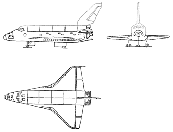
Mentioned features and our country’s orbiter creation experience defined BURAN appearance and its complex-rational aerodynamic configuration. The orbiter is a tailless airplane with vertical tail center placement (Figure 1).
Canopy cabin module, providing the ability of visual landing, fuselage middle part, prescribed by the PLB module (4.6 × 18 m) geometry, rear part, where propulsion unit with RCS external blocks is installed, - formed orbiter’s external lines and defined ground cut area.
Swept-back airfoil, integrated with the fuselage, low position forms general airfoil that meets longitudinal balancing (during hypersonic speeds) and heat shield (when going through heat barrier) requirements. It also provides the most suitable configuration and load carrying construction scheme of the plane. Low-wing monoplane scheme can provide screen effect full usage when landing and runway surface approach.
Pitch, roll and yawing aerodynamic control devices are usual ones for tailless airplane; they are two-sectioned elevons on wing cantilever and a rudder on the fin. Besides them the orbiter has two additional control devices usual for aerospace glider.
The balancing flap, that looks like the fuselage continuation when in initial position is installed on fuselage after body cut edge. The flap is used in order to correct balancing position of the elevons and their unloading when changing center-of-gravity position in prescribed range.
The rudder is a splitting one and when opened it works like an air break.
|
|
Figure 1. BURAN orbiter aerodynamic configuration |
This makes it possible to control flight path and velocity by aerodynamic Drag (and so by Lift-to-Drag ratio) changing during non-powered gliding. The air break is situated in the upper half and when opened it provides moments for a pitch up. Their parrying with the use of the elevons leads to extra lift force during landing and excludes usual for tailless planes loses on balancing.
Aerodynamics and Maneuverability
Orbiter flight is divided into two stages (due to control system) – descent stage and landing stage. The border between them is 20 km height. But from the other hand (from aerodynamic and flight path control ability positions) we can find three flight stages usual for aerospace vehicles.
The first stage (or initial one) is a hypersonic gliding stage with 30 - 40o angle of attack that meets necessary aerodynamic Lift-to-Drag ratio (if Mach number is 28…10). Permissible angles of attack depend on constraints, connected to maximum permissible temperature for thermal heat protection materials. The maximum speed is also limited depending on the orbiter flight height.
The second flight stage is the stage of transition from hypersonic speed range and angles of attack to supersonic speed range. The stage covers 10 - 2 Mach numbers and 40 - 10o angle of attack. On this stage there is no heat protection constraint, angle of attack changes in accordance to the program, that is chosen taking into account many aspects. The program is some kind of a compromise between maneuverability and orbiter control requirements.
The third flight stage (or final one) covers the flight on less than 22 - 20 km height with supersonic and subsonic speed and with 0 - 20o angle of attack. During the stage angle of attack is limited by critical constraints, within which lift capacities and controllability is still enough for normal flight (taking into account automatic control system’s ability for normal work).
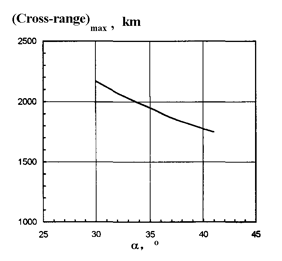
Maximum cross-range requirements (up to 2000 km) are defined with taking into account orbit circles number minimization (from which landing becomes impossible on the territory of our country) and emergency landing providing from the first circle for high orbit inclination.
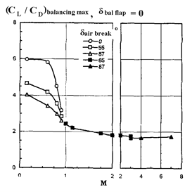
Orbiter’s maximum maneuvering abilities depend primarily on its maximum aerodynamic Lift-to-Drag ratio, shown on Figure 2.
|
|
Figure 2. Maximum aerodynamic L/D ratio depending on Mach number |
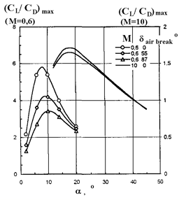
Hypersonic gliding stage is the most important for cross-range capability. At this stage trajectory and energy dispersion control and is done only by roll angle changing, when angle of attack is constant. The orbiter’s Lift-to-Drag ratio (taking into account pitch balancing) should be in 1.05 – 1.40 range, when angle of attack is about 40-30o (Fig. 3, 4). If Lift-to-Drag ratio is in this range, the longitudinal g-load is at low level and this provides the crew ability for manual control.
After cross (lateral) maneuvering and entering airdrome area the orbiter must perform pre-landing maneuvering, approach and the landing itself. The most important problem is the ‘problem of last inch’ (highly accurate landing from the first try controlling permissible kinetic energy level, limited by the runway length, undercarriage characteristics and break devices).
The main characteristic feature of the orbiter flight final stage is the necessity to take into account the atmospheric disturbances at less than 20 km height, especially at subsonic speed when the orbiter goes through tropopause and near-ground layer. These areas (as thermodynamic and wind disturbances model developed by TsNIIMACH and TsAGI together with NPO MOLNIYA shows) is characterized by sufficient current wind flows, wind shift and huge turbulence.
|
|
Figure 3. Aerodynamic CL/CD ratio depending on angle of attack at balancing conditions |
Landing speed is restricted - it must be not more than 360 km/h at maximum landing mass. The wind disturbances in near-ground layer define landing speed range Vlanding = 280 – 360 km/h. This together with angle of attack reserve (up to its critical values) and pitch angle requirements (during touchdown) define necessary level of orbiter lift ability and influence on wing square, geometry and shaping choice.
|
|
Figure 4. Maximum cross-range depending on hypersonic angle of attack |
|
|
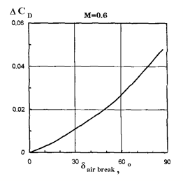
Figure 5. . Increment of the drag coefficient depending on air break opening angle |
The other aerodynamic requirement is connected to the necessity to compensate at landing the wind disturbance effect and miss-speed, accumulated while pre-landing maneuvering. At the final stages of the flight it is not enough to control only speed vector orientation. It is also necessary quick and direct control on the speed value (module). This problem is solved due to the air break choice efficiency. The testing showed that longitudinal acceleration changes (when following wind or headwind) must be fully compensated by 25 – 30% aerodynamic drag change about orbiter’s drag at middle air break angle opening (Fig. 5).
If the situation at landing approach is the worst one when or at headwind landing (when the danger of undershooting exists) balancing the maximum of CL/CD ratio (the air break is not opened) is about K = 5 (Fig. 3).
So the designers were to provide the orbiter with necessary aerodynamic CL/CD ratio and lift capacity level. In order to do this they had to analyze wing shape and fuselage edges influence on the characteristics, to consider interdependently the requirements to characteristics of aerodynamic forces and aerodynamic moments and requirements to the airframe heat protection working conditions. The experience of hypersonic flying vehicles research in a wide range of Mach number and angle of attack, and orbiter preliminary parametric research made it possible to choose as the base one a trapezi-form wing with aspect ratio of λ = 2.25, sweep of χ = 45° along front edge, profile of 12% thickness and high sweep wing glove. This choice became the base in the problem to satisfy all the requirements to aerodynamic configuration in hypersonic, supersonic and subsonic range f flight.
It is necessary to mention that small wing aspect ratio, being effective at low Mach numbers, leads to high angles of attack when subsonic speed. That’s why the questions of controllability and lift capacity reserve on the angle of attack near critical stalling numbers were studied thoroughly. When deciding the shape of the wing, much effort was spend in order to get good results on supersonic, transonic and subsonic speed of the flight. More over, heat protection elements installation on the elevons has blunted rear edges. Such deformations have worsened the characteristics, increased wave loss and requested its finalizing, especially when supersonic Mach numbers. The wing shaping, as it is known, doesn’t influence on orbiter lift capacity when hypersonic speed.
Aerodynamics and Controllability
Orbiter control and stabilization problems when atmosphere flights are connected with orbiter aerodynamic stability and moment efficiency of aerodynamic surfaces.
The first and clear requirement to aerodynamic pitch moments’ value and changing character (with neutral and turnout control devices) is longitudinal balancing providing at every stage of the flight with designed range of center-of-gravity position (in longitudinal axis xc.g. = 0.64-0.66 Lfuselage, i.e. with 2% dispersion from fuselage length Lfuselage).
One of the most difficult problems was to provide necessary pitch moment dependency on angle of attack at the whole range of Mach number.
There have been done the works on wing geometry, its shape and wedging, as well as on fuselage nose and rear study. The results have made it possible to ensure near zero pitch moments, pressure center (at hypersonic speed) and aerodynamic focus (at supersonic and subsonic speed) position when the following requirements were applied to different flight stages:
- needed level of lift capacity;
- airframe self-balancing (mz ≈ 0 for middle center-of-gravity at α = 40…30°, M ≥ 10);
- minimum required control device deflection for balancing;
- pitch moment changing of neutral and stable character as a function from angle of attack at different flight stages;
- minimum focus takeoff run when going from supersonic to subsonic Mach numbers.
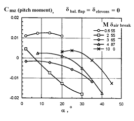
Longitudinal aerodynamic moment curves on Figure 6 are corresponding to the middle center-of-gravity position xc.g. =0.65 and air break opening program depending on Mach number: δair break = δair break program (M).
|
|
Figure 6. Pitch moment coefficient depending on angle of attack and M |
An important question, when solving the balancing problem at hypersonic speed, was a cylindrical undercut at low rear surface (Fig. 1). This change in configuration has made it possible to increase aerodynamic L/D ratio at subsonic speed and to improve undercarriage layout and construction.
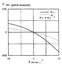
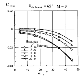
Pitch moment change can be done by elevons, balancing flap or air break deflection. We may use all these aerodynamic control surfaces like one integrated device for longitudinal balancing and to change during the flight each other functions taking into account its features and influence on the rest aerodynamic characteristics. Such control is the most effective at hypersonic speed where aerodynamic forces are proportional to surface’s angle of attack squaring. That’s why the balancing position of every device effects on not only its moment efficiency (gradient by angle of deflection – Fig. 7), but also on the airframe stability (pitch moment gradient by angle of attack – Fig. 8).
|
|
Figure 7. Pitch moment coefficient increment depending on elevons deflection at different hypersonic angles of attack |
|
|
Figure 8. Pitch moment depending on angle of attack at different elevons and balancing flap position (xc.g.= 0.65) |
|
|
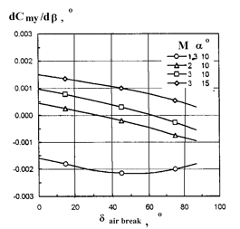
Figure 9. Yawing moment gradient by slip angle depending on air break opening angle (xc.g. = 0.65) |
Elevons are control and stabilization devices for both pitch and roll channels. That’s why they must meet to the requirements of quick action. When solving balancing problems, elevons must be minimally loaded and correspond to quasi-optimal conditions, chosen by the criteria of their efficiency in every channel, airframe stability at given angle of attack range and taking into account the hinge moments requirements.
The balancing flap, as it was said before, is intended for elevons’ quasi-optimal condition providing by their deflection reducing when longitudinal balancing. The balancing flap position doesn’t effect very much on the aerodynamic Lift-to-Drag ratio.
The air break opening (that provides moments for pitching-up) isn’t used so much for longitudinal balancing. Its influence on feathering (yawing) stability on slip angle and rudder moment efficiency is more important (Fig. 9).
Saying about orbiter stability and controllability it is necessary to mention two features that connect aerodynamic designing (with automatic control system development that can provide necessary dynamic characteristics) with its structure and parameters. The first one is intentional refusal to provide longitudinal and feathering stability on angles of attack and slip angles by aerodynamic configuration means at different stages of the flight. At decreasing Mach number from hypersonic to supersonic we change the pitch moment curvature sign because of changing in the streamline flow along wing’s upper surface.
If the flight range of M = 4-3 and α = 15-10° a zone of weak local instability on α angle (Fig. 6) is appeared. In transonic area (M = 0.95-0.9) the airframe is usually unstable and weakly unstable at subsonic speed in case of more rear center-of-gravity than designed middle one (xc.g. > 0.65). The airframe is also unstable on angle of attack because of destabilizing influence from fuselage forebody and fin shading at supersonic and hypersonic high angles of attack. But its lateral dynamic stability (at angular motion around center of mass in the bank and yaw channels) is provided as a result of rolling stability on slip angle.
The second feature is connected to the orbiter reaction changing on roll when elevons are deflecting (at angle of attack of α >15° and M>3). This reaction is changed backward from the straight line to the opposite sign reaction due to development of the slip angle. This leads to the rotation in the opposite direction because of rolling stability. The elevons are used only for stabilization task at these flight stages (at high supersonic and hypersonic speeds).
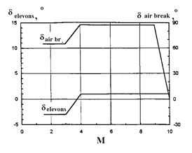
These characteristic features, as well as the influence on aerodynamics from the elevons and air break deflections, have led to the necessity to take a quasi-optimal program dependency on Mach number for these devices deflection (Fig. 10).
The program, chosen for elevons, has provided the most rational levels of longitudinal stability at angle of attack change, the moment efficiency in pitch, roll and yawing channels, and hinged moments’ minimization. Air break opening program has provided maximum reasonable lateral stability on slip angle and rudder efficiency and also additional pitch moments, necessary for elevons program realization. At subsonic flight stages (M < 0.8) the air break is used only for speed control.
|
|
Figure 10. Elevons and air break position programs at pitch balancing |
At designed elevons and air break programs the longitudinal pitch balancing is provided by the deflections of balancing flap.
Mentioned features reflected on the interaction between the RCS engines and the aerodynamic control devices.
At the first stage the elevons are put on for the orbiter’s balancing and statistic components relieving in the commands for the RCS control engines operation. Then when speed becomes higher, transition to aerodynamic control devices is done and one-by-one cross (q = 50 kgs/m2) and longitudinal (q = 100 kgs/m2) the RCS channels are put off. The yawing channel engines work for stabilization and ‘inverse’ control (slip creation with later roll rotation) till transonic speed achievement.
It is quite clear that elevons and rudder must have moment efficiency (besides balancing providing about three axis’) being enough for stabilization in atmosphere disturbances and for the orbiter’s control with high running speed and minimum aerodynamic loads (hinge moments). This is very important when doing pre-landing maneuvering, approach and landing itself.
As the orbiter’s makes unpowered gliding irreversible flight expanding only energy and must land very accurate in the first try, maneuvering and control requirements during this stage of the flight are very high because of time limit (landing from 20 km height takes less than 10 minutes).
The researches, conducted by NPO MOLNIYA together with TsAGI, have made it possible to form strict evaluation criteria for stability and controllability characteristics in flight of limited time. Many directional researches on dynamics of flight have included mathematical modeling and stand simulation. The results have shown the enough (for successful flight) efficiency of elevons, rudder and air break in the tasks of control on normal g-load, roll angle and velocity.
Aerodynamic Configuration Development Main Stages and Methods
The most difficult problem of aerodynamic designing was configuration development in order to clarify orbiter geometry and define its real aerodynamic characteristics. Configuration difficulty was because of its uniqueness quite normal for BURAN orbiter and unprecedented for flying vehicles. During atmospheric stage (less than 100 km height, where aerodynamic forces and moments influence on the flight) the orbiter is descending through the speed range beginning from orbital velocity (M = 28-27) to light subsonic speed when landing (M = 0.28-0.22. Therefore, it was necessary to study the new questions about aerodynamics both in free-molecular gas flow (during the initial atmosphere entry) and in real air flow that is usually accompanied by dissociation, plasma forming and viscous interaction with border layer at hyper velocity and upper altitudes. It was always difficult to study supersonic wing streamline flow with high relative width profile at about 107-108 Reynolds numbers. The problem was even more difficult because at hypersonic velocity, as a result of high breaking temperature, non-equilibrium physical and chemical processes (that can’t be modeled in aerodynamic tunnels) took place in shock layer. These processes lead to pressure center deflection, pitch moment changing and influence on longitudinal balancing. It is necessary to mention also such features as low aspect ratio of the fuselage and large bottom cut square. The fuselage forebody rounding and wing and wing glove front edges are of large radiuses. The wing profile is of high relevant width (c = 0.12), rudder is splitting into two doors to solve the task of air break. The airframe’s surface isn’t ideal and has stepped heat protection shield. Special air-gaps cut this shield for temperature compensation.
In order to solve mentioned problems it was necessary to use all the experience got in science, technology and experimental fields. It was also necessary to find new methods of numerical calculations, create experimental base and measuring instruments. The problems would not been solved without automated tests and data processing.
Aerodynamic configuration analysis and synthesis, aerodynamic characteristics forecasting and determination were made step-by-step with difficulty and work done increase.
During the first stages when the appearance of the orbiter was being formed, different versions of configuration were analyzed to ensure the basic technical requirements. Then the reference configuration has been chosen.
Summarized aerodynamic characteristics’ determination, control device efficiency and other data in the volume necessary for preliminary construction load-carrying scheme, control system, flight dynamics calculation etc choice was done with the use of calculating and theoretical methods. The computer program complex, based on main physical phenomenon modeling, was created. Besides this, a simple numerical method for engineers was used. It was based on the wind tunnel results for lifting body, usual and hypersonic plane prototypes’ configurations. That data have consisted both of prototypes’ summarized and airframe units’ characteristics (fuselage, wing, fin and control surfaces in the whole range of Mach number and angles of attack).
In whole the calculating complex made it possible to define quickly and with a rather good accuracy necessary aerodynamic characteristics at any speed and height.
It is necessary to mention TsAGI great contribution to development and introducing of numerical and theoretical methods and programs.
Many experimental models were tested in aerodynamic tunnels (at hypersonic, supersonic, transonic and subsonic speed) in order to clarify and optimize airframe characteristics. The tests results showed profile form, trapezi-form and wing glove, sweep-back of leading and trailing wing edges, wing inclination and dihedral, fin and control surfaces geometry, fuselage fore-body and after-body outline changes, external elements influence on characteristics.
The main result was that all the geometry characteristics of the configuration were clarified. The final aerodynamic development was done by experimental method with the use of final models together with numerical accompanying complex that could take into account the factors that can’t be modeled in aerodynamic tunnels.
The critical stages of the flight were studied thoroughly:
- at upper heights (H = 100-40 km), Mach numbers (M = 28-10) and angles of attack (α = 40-30°) because of thermodynamic air features and shock wave interaction with border layer;
- at transitional angles of attack (α = 30-0°) at high supersonic speed (M = 5-3), for which it is normal wing upper half streamline flow changing and vertical tail shading;
- at transonic speed (M = 1.3-0.7), for which it is normal shock wave phenomenon on high relative width blunted profile and depending on this streamline flow structure changing;
- at approaching the ground and landing where runway surface influence as a shield is very important.
It was also important to study the RCS influence on airframe streamline flow when engine jet interacting with inflow. This factor was obvious when new moments appearing that change orbiter’s reaction when RCS control engines operating. The factor was taken into account when developing control devices.
Much attention was paid to the hinge moments at elevons sections, rudder, air break and balancing flap determination (M < 5).
The tunnel tests in order to define aerodynamic correction in air speed and height at transonic and subsonic speed direct measuring system was held. It was necessary when developing control systems.
During aerodynamic configuration experimental development, there were developed and tested many different models in NPO MOLNIYA.
There have been created the following aerodynamic models:
- for weight testing (including the models remotely controlled surfaces);
- with the strain gauged measurements (cooled and non-cooled) for airframe elements and control surfaces loads determination;
- venting models (the combination of the last two types that made it possible to unite their total and distributed characteristics);
- damping and spin characteristics determination models;
- the RCS engines work simulating model.
Many wind tunnels tests were made for more accurate and safe orbiter aerodynamic characteristics’ determination. But it is well known that many phenomena can’t be simulated in wind tunnels. Mach and Re numbers real ranges and their combinations, gas flow composition and its temperature can’t be also produced in the wind tunnels.
That is why numerical methods were very important. They made it possible to supplement experimental data base at the last stage of aerodynamic characteristics refinement with the corrections that took into account flow viscous interaction with boundary layer at upper heights and air dissociation when high breaking temperature at hypersonic speed.
Air dissociation calculations, showed a significant pitching-up moment, were the result of TsAGI specialists’ fine work. They were able to take into account the fact (and with fine accuracy) that can’t be produced in the wind tunnels. By doing this they relieved themselves of the troubles that have to do with the orbiter balancing when going through a high temperature leg of trajectory.
The last stage of aerodynamic configuration development was flying testing with the use of BOR-5 flying model and BTS-002 full-scale flying analogue. The last one is able for independent takeoff.
BOR-5 flying vehicle has the same geometry as BURAN orbiter and is made in 1:8 scale. It is flying controlled aerodynamic model that can face high Mach numbers and dynamic pressure and the model can make it possible get angles of attack, M and Re numbers and their combinations, orbiter descent trajectories in range of M = 16-4 and Re = 106-107 in real time.
Flight tests results have clarified basic aerodynamic forces and moments characteristics, defined balancing and stability (for prescribed angles of attack at hypersonic speed range) parameters and control devices efficiency and hinge moments. The important thing was also correction, taking into account air real characteristics.
The BTS-002 flying analogue, able to take-off independently, was created to work out automatic pre-landing maneuvering, landing approach and landing modes. The models of BTS-002 were tested in wind tunnels. The results have discovered minor differences of BTS-002 from real orbiter in aerodynamic lift and pitch moment coefficient at zero angle of attack. These differences are explained by the turbojets installation for take-of purpose.
The results of identification procedure have shown a good coincidence of real and forecasted aerodynamic characteristics in M < 0.6 range. The main result that was made during flight tests the confidence in forecasted BURAN aerodynamic enough for its first flight.
Besides the orbiter’s aerodynamic analysis in autonomous flight the most important problem that have to do with much work done together with NPO ENERGIYA was solved. It was necessary to research the orbiter’s aerodynamic interference with ENERGIA rocket launcher in joint flight at climbing stage and injection into orbit. It was also to research the orbiter with the central rocket block at return maneuver trajectory as an effect of abnormal situation appearance. The decision of the problem defined loads on the link junctions and airframe units. It also defined dynamics of abnormal maneuver and urgent separation when returning at emergency.
Besides interference research it was necessary to analyze the orbiter aerodynamic characteristics at high supersonic and hypersonic speed in wide range of angles of attack (α = +50 … -30°) and slip angles (β = +20 … -20°).
In order to provide such tests special models of the orbiter and rocket launcher with build-in strain-gauge balance were done.
Automated stands for the simulation of rocket and orbiter relative motion when tunnel tests for separation process. The specialists faced many difficulties when developing suspension devices for models testing at high angles of attack.
The tests made in aerodynamic wind tunnels have provided the designers and constructors with initial data necessary for joint flight and abnormal separation all problems’ solving.
In whole the volume of experimental and calculating work done by the specialists during the orbiter aerodynamic designing was very large for our country practice. The computer program complex for aerodynamic characteristics was created. The numerical results correspondence to real ones was confirmed by not only tunnels’ experiments, but also by successful flying tests of hypersonic BOR-4 and BOR-5 flying vehicles.
There was developed 85 different (by difficulty and scale) aerodynamic models, 122 strain-gauge balances for them, as well as 12 unique automated stands for tests in tunnels, special measuring means and data processing automated complexes. The number of tunnel experiments was 36630. These tests were conducted in 25 different tunnels, i.e. practically in every one tube in the country.
The full complex of aerodynamic characteristics was presented in special book and was later refined for three times. The last improving was made officially just three months before the orbiter launch.
All the aerodynamic characteristics were presented in a very convenient form for use and work. Any user can take them at any volume.
The BURAN orbiter’s aerodynamic characteristics data bank (database, stored in the computers) was formed for data unification, their accuracy and wide automation of design research providing.
Aerodynamic Characteristics Reliability Estimation
The important prediction phase of the aerodynamic characteristics is the transition from design-experimental data obtained in ground test bed conditions to the characteristics appropriate to real flight conditions. As was mentioned above, it is absolutely impossible to simulate in the wind tunnels at same time real conditions on M and Re numbers, gas flow structure and the boundary layer condition. In addition, the tunnel results include instrumental and methodical errors, reflect influence of flow quality, the tunnel’s working field loading and other. All these factors lead to uncertainty in nominal values of the aerodynamic characteristics, obtained experimentally. The same is possible to tell about all design-theoretical methods, in which the analyzed objects are considered with a number of simplifications.
At the flight tests stage it is necessary to consider the BURAN orbiter’s any flight, including the first one, as an actually operational, because every flight passes trough all the altitude and speed range and practically under the nominal time schedule and finishes by normal landing. During the flight maximum safety and minimum risk requirements are compulsory ones.
Because of an extraordinary complexity and a high cost of every flight, the realization of the flight tests by conventional methods series, ‘step-by-step’ conditions complication and expansion of flight stages is impossible. All problems should be solved at preflight ground orbiter’s working out.
These circumstances have predetermined the new approach to aerodynamic researches, have highlighted the problem of maximum exact aerodynamic characteristics’ definition before flight, that resulted in necessity of an estimation on their ratings confidence. For the first time in domestic practice, ranges of possible change supplemented all aerodynamic characteristics’ nominal values.
The values of the tolerances were determined by errors of tunnels’ experiments and computational methods of rectification on the not modeled factors accuracy, by results of data comparison both the tunnels’ tests and planes (and some types of flight vehicles) that were adopted as the prototypes. The estimation of reliability ranges was conducted in different directions and by different methods.
As the main source of the aerodynamic characteristics obtaining was tunnels’ experiment, the detailed examination of wind tunnels was conducted and its results have demanded realization of different models blow in different tunnels, on different test equipment and in different research centers.
The results of the accuracy tests analysis of one model in different tunnels, different models in one tunnel, reproducibility of the results obtained on different techniques allowed to estimate experimental dispersions and to form their envelopes.
At an estimation of the aerodynamic characteristics’ accuracy, the analysis of divergences of the tunnel data and flight tests from experience of domestic aircraft was conducted. Unfortunately, this analysis was not a compulsory element of flight tests technique. That is why systematized materials number was not large. More over, all the estimations were concerned to the well-studied area in already reached Mach numbers’ range (M ≤ 3). The experience got at the analysis hypersonic flying models’ BOR-4 and BOR-5 flights was more important. The divergences between the characteristics, predictable ones and obtained during the flights, were submitted depending on a Mach number and were taken into account in a total estimation.
To obtain a final knowledge about boundaries of the aerodynamic characteristics’ reliability, a joint group of specialists have been formed. The representatives from TsAGI, LII and NPO MOLNIYA have conducted linkage of all the materials, corrected design-experimental data and flight tests results, analyzed all errors and divergences despite of distinctions in the approaches to this problem, formed unified opinion on the aerodynamic characteristics’ reliability ranges boundaries.
The values of the tolerances on aerodynamic coefficients’ ratings as relations to a Mach number were brought into the database and accordingly into the reference data bank.
Flight control system developing was conducted simultaneously with refinement of the aerodynamic characteristics. That is why steadfast attention NPO MOLNIYA and TsAGI, NPO AP and MARS Design Bureau specialists was given to the analysis of design cases, i.e. critical combinations of deviations from ratings determining limiting capabilities of maneuvering and maintenance of stability and controllability by means automatics.
It should be noted, that the accuracy of the aerodynamic characteristics essentially influences on overall performance of the control system. The control capabilities are limited by power capacity and dynamic responses features of drives control systems, necessity of taking into account failure conditions, probabilities of external atmospheric disturbances, indefiniteness in other input datum.
The important factor accompanying the designing was simulation of the flight dynamics, during which the zones of heightened sensitivity to change initial datum and aerodynamics ones were determined.
The activity on an outcome of ‘bottlenecks’ has resulted in necessity of additional repeated tests in the wind tunnels with the purposes tolerances values refinement only in detected critical zones. Such approach considerably reduced the volume of aerodynamic researches. The most difficult was the Mach number range of M = 6 - 2 and transonic range.
The account of the tolerances on the aerodynamic characteristics resulted in structure adjusting and optimization of flight control system settings; that lowered its sensitivity on all the field of disturbances and ensured the necessary flight safety.
BURAN Orbiter’s First Flight
On November 15, 1988 BURAN orbiter had made in full automatic control mode its first space flight (205 minutes) having put a beginning to a new direction in domestic astronautics development - the creation of reusable aerospace flying vehicles.
The successful fulfillment of the flight and high-accuracy landing in conditions of the meteorologists storm warning allows to make a conclusion that in the preflight aerodynamic characteristics obtained as a result of the complex design-theoretical and experimental researches extensive program fulfillment, we can consider authentic enough.
The analysis flight results are of an independent interest and are explained below briefly.
|
|
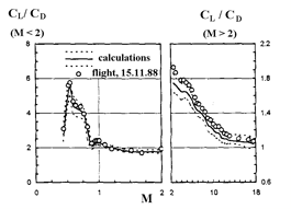
Figure 11. Actual and designed balancing aerodynamic CL/CD ratios |
The complex processing of external trajectories measurements, telemetry information, results of atmospheric sounding and meteorological conditions data allowed to define aerodynamic forces, moments and balancing aerodynamic characteristics of the airframe in actual conditions of real flight and compare them with designed ones, defined on preflight aerodynamics.
In altitude range H = 65 - 20 km (M = 17,6 - 2) the actual values of the lift coefficient CL systematically exceed design ones on 3 - 6 % and lay within the limits of the tolerances. The values of a drag coefficient CD agree with nominal values.
At Mach numbers M > 13 the designed and actual values of aerodynamic balancing CL/CD ratios agree among themselves, at M = 13 - 2 (above design on 5 - 7 %) and are near to the upper boundary of the tolerances (Fig. 11). The maximum differences up to 10 % take place in Mach numbers M = 3,5 - 2. At M < 2 actual values CL, CD and CL/CD agree with nominal values.
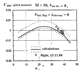
The given program rule of elevons was practically sustained. At Mach numbers = 17,6 - 10 pitch moments are a little bit higher if compared with designed ones, but do not fall outside the tolerance limits (Fig. 12). The greatest divergences in balancing are marked in M = 10 - 6 range, where the balancing flap when unloading elevons, went on a maximum angle. In the transonic zone of Mach numbers M = 0.95 - 0.9 the orbiter’s pitching-up was more vigorous, than it was forecasted.
|
|
Figure 12. Pitch-up moment’s actual and design values |
The identification of the aerodynamic moments derivatives determining stability and controllability, are made in a limited volume and have only estimated character, as in the first flight special test maneuvers for obtaining the exact estimates in order to prevent risk, were not conducted. The transient processes connected to control were treated only. The values of estimations of derivatives lie within the tolerance boundaries.
The Final Remarks
The short review on main aspects of the BURAN orbiter’s aerodynamic designing allows stating some judgments about experience and about readiness to solve the problem on creation of new samples of space vehicles.
In NPO MOLNIYA and scientific institutes, first of all in TsAGI, aerospace flying vehicles (AFV) aerodynamic configuration methodology was developed. Its scientific- theoretical and experimental development, the requirements on maintenance of aerodynamic perfection, stability and controllability, and also on a necessary structure and quality of input datum on aerodynamics for the solution of all flight dynamics complex problems and designing were worked out.
The method of engineering analysis for the flight with use of aerodynamic was tested practically. The method allows forming and realization the requirements to the AFV aerodynamics, maneuverable capabilities and dynamics of flight as a whole, and also to constraints, connected to heat protection and strength.
Much progress in designed (reference) case’s understanding is very important, as well as new knowledge about critical questions and the ways of their solution in the problems of controlled descent with use of aerodynamic lift, balancing, stability and controllability maintenance.
In the whole, the activity on the ENERGIA-BURAN project confirms a capability of flight tests results forecasting on the base of preflight aerodynamics and flight dynamics ground modeling.
The gained experience allows beginning aerospace vehicles’ creation of the next generation.