

- Documentation
- Table of contents
- AKC
- Introduction
- Airframe Creation
- Technological Problems
- Experimental plant
- Building plant
- Conf. Development
- Aerodynamic Designing
- Algorithms of control
- Guidance & control
- Stand for training
- Training center
- Horizontal flight tests
- Crew on board
- Auto Landing complex
- Structure
- Payload bay
- Metallic material
- Non metallic material
- Non metallic material
- Cabin assembly
- Thermal designing
- Thermal protection
- Heat protection
- Quartz fibre
- Computer designing
- Gas's dynamic
- Strength
- Basic direction
- Tech. preparation
- Technical diagnostics
- Methods & means
- Radio nav. support
- Information & controls
- Control of onboard equ.
- Electric power dist.
- Electromagnetic
- Antennas installation
- Auxiliary power unit
- Hydraulic system
- Cabin
- Safety
- Air transportation
- Automatic landing
- Exp. working out
- Return to space
- SPIRAL
- Analysis of concept
- Horizontal take-off
- BOR-4 & BOR-5
- MAKS multipurpose
- MAKS-D
- Thermal design
- Gas & thermal design
- Wing deflection
- Flight performance
- Maks structure
- Metal materials
- Advanced non metallic
- Information provision
- Onboard starting comp.
- Onboard control comp.
- Control organization
- Aerospace systems
- Economic investigations
- Triplane aircraft
- Technical inventions
- Scientific potential
- Triumph and tragedy
- Birds of a Feather?
- TsAGI wind tunnel
- Bibliography
| -The Mriya is destroyed. |
| -Shipping of Buran-KS to Sotchi. |
| -Antonov is no more. |
| -Buran is now a museum. |
| -New pictures of the blogger Ralph Mirebs. |
BURAN Orbital
Spaceship Airframe
Creation
Computer-Aided Systems of Designing, Mathematical Simulation
and Manufacturing of BURAN Orbital Spaceship
Dr. Osin M.I.
The designing methodology is described, computer technologies application and the basic directions of BURAN orbiter design and manufacture computerization are shown. The tasks of mathematical simulation of operational modes and computer-aided production processes set in accordance with the paperless technology are described.
Computer-Aided Designing (CAD) systems, providing creation of BURAN Orbital Spaceship’s (Orbiter’s) airframe, is an illustrative example of new technologies, generated by aerospace issues.
No creation of BURAN orbiter would be possible without application of the computer-aided systems’ to the following tasks: unified computer model of contouring, automated process for the Thermal Protection System’s (TPS) tiles production, automated mass control etc. In general we can say about the new designing methodology based on automation of all processes beginning from designing and up to manufacturing.
The orbital spaceship was a completely new object both for aircraft, and space-rocket engineering. So, Orbiter airframe’s creators were resolutely targeted at usage of all technological potential of the country. More then two hundred scientific and industrial organizations were engaged and joined their efforts for development of new control systems, drives, materials, engineering processes and test facilities under the requirements specifications set by NPO MOLNIYA.
The essentially new methodology of designing was developed under the banner of comprehensive approach to each problem, including monitoring its aspects from scientific idea to design implementation and its realization in new materials, engineering processes and certification tests. A through mathematical methods application to all stages of development was an important feature of the methodology. A system approach was generated at Orbiter designing based on the analysis and simulation for a set of target tasks, taking into account various operational conditions. The composition and structure of the considered object have to be optimized at all levels.
The discussion of uncertainty and technical risk factors became the norm in design documents and at technical meetings.
The fact that the first mass summary for the BURAN airframe systems had the accuracy of six percents is an evidence of high culture of designing.
The creators of BURAN orbital spaceship have introduced a high technological culture, readiness for innovative designer solutions, aviation principles of guaranteed provision of reliability from their aircraft enterprises. The space-rocket industry experience was also used, in particular, the knowledge about space flight conditions and methodology of multifold mathematical simulation for the designed object motion at different stages of flight. All this experience was worked through and used. The essentially new amalgamation from science and practice of design work was born on its basis. There were as primary taking into account the following requirements to an extraordinary object:
- completely automated airplane;
- creation on the base of the most new materials and technologies;
- independent operation in space;
- thermal and vibration loads, unusual for aviation.
Therefore the subdivisions of NPO MOLNIYA, working in different direction, and the head department on computer-aided design systems service have formed a joint network structure which was staffed with young and the most gifted graduates from leading institutions of higher education of the country.
|
|
Figure 1. Computer drawing of a rod-brace |
The way of development and application of computer means implemented by space corporations of the USA was analyzed. In the shortest time, a computing base was organized which was unusual even for the leading (at that time) aircraft industry.
Domestic computers, which were really powerful for the time being, were included in its structure: BESM-6 (later Elbrus-1), a series of ES computers including the most fast ES-1066, dozens of graphic stations for automated working places, including Bulgarian IZOT stations (VАХ systems analogues). A supercomputing device with VАХ-8600 graphic stations appeared later, and then a saturation of the firm with personal computers of Pravetz series began.
Outfit with computers has increased by 100 times (up to 200 … 300 thousand operations per second per engineer) for 7 years (from 1977 to 1984), and subsequently, each engineer became a user of computers and every second engineer – a programmer.
The developments of application software were centralized, and the leading scientific centers of the country such as TsAGI, NIAT, MGU, Ukrainian and Belarussian institutes of cybernetics, MAI, MATI, NIIAS and others participated in them.
The inevitable modernization was taken into account (there were three waves of computer types changing), and programs were generated invariantly to general-system maintenance of computers.
NPO MOLNIYA reached leading positions in the branch, which was marked by inter-branch commissions at acceptance of the first (in 1982) and second (in 1990) release of CAD (Computer-Aided Designing) system. The best level of design and construction work automation (50%), achieved in the branch, was added with a mass transfer of documentation to production without supplying it with drawings, but on computer carriers which allowed to obtain computer programs of processing contour-making details. It was extraordinary even for aircraft industry.
In Design Division, including CAD Head department, a software package was created to integrate subject modules referred to separate design branches. The original programs synthesizing optimum structures were created with allowance for the factors of uncertainty intrinsic to aerospace designing.
These developments were reflected in the first domestic books on CAD for flying vehicles.
The classical approach of finite-element simulation was processed and fused with the original programs of mass distribution among load-bearing elements in view of static and dynamic loading.
|
|
Figure 2. Computer Drawing of a Rib Section |
At dozens of plants, scientific centers and test organizations including the maintenance area of launching site, the unified information model of the Orbiter’s contouring was organized. Three production plants and two joint design bureaus were engaged in monitoring system of the mass-inertial characteristics.
The computerized onboard complex of monitoring and control was created to maintain high reliability. Thousands programs were generated for all nominal and emergency situations for that purpose with use of specialized software. These programs were tested on unique simulating ground-based stands of equipment and units of the whole airplane. Powerful computers of unified system worked on these stands to support the flight simulation. A special attention was given to creation of computer-aided test and diagnostics systems both in production and in maintenance.
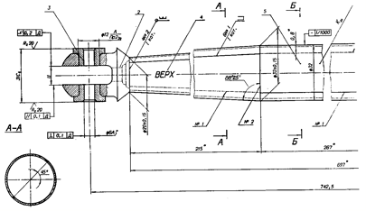
The CAD system had been really applied to development and production of rods-braces, ‘stitching’ walls of frames and spars and ensuring spreader efforts and fastening aggregates of the Orbiter (Figure 1). It was the first in the branch (in 1978).
The optimization by mass criteria was conducted in view of all conditions of loading and with the tips for attachment sizing.
Designers executed research to reduce the quantity of die blocks and to reduce the work cost due to minor refusals from optimum by mass solutions for the whole lot of 180 full strength braces per orbital aircraft.
As a result of comparing composite, aluminum-beryllium and titanium braces, preference by cost was given up to the latter (practically without aggravation of mass characteristics). The technique of parametric selection for size-types of complete sets of braces for each separate aggregate was created.
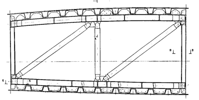
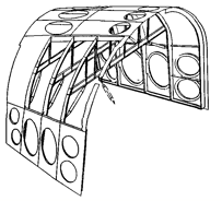
The computer drawing for one of such units is shown in Figure 2. The highest level of designing automation (70…80%) was reached at development of the nose RCS engines bay (Fig. 3). For standard parts of airframe framework (brackets, adapters) an integrated subsystem of designing and manufacturing was created.
Layout of control positions, change of pilots’ orientation when in orbit, possible actions of operator-installer were studied with application of geometric antropometric model of the pilot.
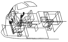
The computer layout of bays differed from similar works, carried out at other firms, by simple and operative data input directly from outline and installation drawings of devices and units. Ergonomic issues and, in particular, delineation of zones of accessibility and visibility boundaries for pilots with the help of computer graphics were studied in view of changes of aircraft orientation at landing.
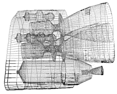
In Fig. 4 and 5, the examples of computer graphics application for the layout of engines block in the rear bay and seats arrangement plotting in the cabin are shown.
|
|
Figure 3. Computer plotting for the nose RCS engines module framework, isometric projection |
The computer designing has united aviation and space-rocket engineering in the tasks of computerized tests, including the full control of operation from start to landing. Mission Control Center and specialized complexes with flying laboratories, working through automatic landing, were involved.
Database of aerodynamic characteristics, covering all stages of flight and basic control modes, were created to support the designing process.
|
|
Figure 4. Computer Layout of Propulsion Unit at Rear Bay |
|
|
Figure 5. Computer plotting for seats arrangement in cabin |
Multifunction software complexes monitoring the operation of onboard systems, as well as design-simulating modules describing streamlining and heat exchange are referred to in appropriate sections of this book.
New scientific schools of computer design and modeling are generated by space topics.
First in our country books on methodology of computer designing flying vehicles were written by developers of BURAN Orbiter. Therefor it is not by surprise, that the basic custom activities on software of forms, modes of descent and landings description, which were accomplished within the programs of Russian and European space agencies interaction, were implemented by experts of NPO MOLNYA.
The most interesting was the activity on creation and deployment of through design and production process. It ensured interaction for several organizations, based on principles of paperless technology in designing forms of airframe’s details and thermal protection. This technology was unique and unusual even for (leading in country) aviation and space-rocket branches, it was the first in Europe too.
The orbiter has a surface of 1025 m2. It has heat protected wing and fuselage leading-edges and is coated with the TPS tiles of ultra-pure and ultra-thin pressed fiberglass with a special coating (~ 800 m2 surface) and mats of synthetic felt. The tiles are turned on special machine tools and should shape the external contours and exactly adjoin to the skin of the airframe.
The tolerance of step between tiles is of ± 0.2 mm in the contour. The inter-slot gap should be within the limits of 0.8…0.6 mm.
The distortions of units’ contours and their joints can be up to 7 mm. The tiles’ width should be kept with deviations under 1 mm. All tiles are curvilinear and have different contours. Long years of laborious work would be required to complete the exact plotting of every tablet in drafting departments.
It would be necessary to engage over 700 designers, estimators, technologists and workers, to issue 40 thousand drawings, data encoding cards for machine tools, to the manufacture and bind models and drafts in case of ‘manual’ work. Such work is unacceptable both by terms and by quality.
Seventy engineers-programmers of three organizations created and organized a completely automated design and production process at Design Bureau (DB) of NPO MOLNIYA and at TUSHINSKY Machine-Building Plant. It is possible conditionally to divide all problems, which the developers of process encountered, into three groups: mathematical, engineering and organizational.
The mathematical problems appeared to be the most precisely defined. For their solution were created, at the first, the techniques of contour-producing surfaces’ description by second-order curves, template arcs, special contours, bi-cubic splines, matrix bi-polynomials were first of all created for their solution. Secondly, the programs of computerized cutting contours with surfaces and planes of general position with generation of normal and bi-normal grids over units of planes tracks interception were developed. Thirdly, there were created the original algorithms of construction of mathematical templates for contour-producing surface by the data of units’ measuring. The algorithms were used for the problems of correction the forms of tiles, where they adjoin to the real distorted external surface of units. Using optimization numerical methods, the automated repeated determination (correction) of the TPS tiles mating surface was conducted on condition of preserving their width, that is at the absence of steps between tiles.
Technical and engineering problems depend usually on failures and low reliability of computer facilities and graphics means. The resolution was found in organizing a through three-shift work of programmers-estimators with step-by-step control of calculations’ outcomes with visualization on screens of monitors, and also by plotting and regular comparing through details: check totals and other certificates of the computational arrays.
All applied software was created invariantly to the types of computers, therefore the change of computing facilities and computer graphics means generations was smooth. The CAD systems have automated designing process in the directions:
- synthesis of units configurations;
- cutting units’ surfaces to belts and panel sockets;
- dialogue formation of complexly shaped non-regular and special tiles;
- display of damping substrates;
- plotting volumetric drafts of tiles cells by a plotter;
- generation of processing (finishing) and control programs;
- calculation of mass and center-of-gravity position.
This CAD technology is opened for extension.
Organizational problems appeared to be the most complicated. Based on paperless technology, the transfer and correction of information on production is organized by delivering fragments of databases on computer carriers and monitoring these procedures by the databases’ administrators. At the same time, the archaic procedures of entering documentation in production under the conventional notices are saved. The listings with arrays of numbers should have reflected document circulation, but were stored dead in departments of the Main Technologist.
Opposite to similar works on the Space Shuttle TPS tiles’ manufacturing and mounting, the information process has appeared to be multi-link. The step-by-step conversion scheme of information data on the shape of tiles’ cells was built. The parametric numerical models of the tiles’ cells are handed over to production plants included in databases, and these models describe not only geometry, but also location and type of the blank, material, coatings, manufacturing process, tool, lathe and gadgets. By results of units’ measurements, the geometrical information is corrected at plants and rewritten into unit technological databases.
The databases make the basis of the through designing and industrial computerized process. They integrate systems of computer- aided design and computerized manufacturing.
Designers, technologists and the databases’ administrators are users of the systems. They obtain the tiles’ and units’ plotting in an automatic mode by means of computer graphics. Then they form the wire-frame and point models for the tiles of intricate shapes, intended for location on edges and joints of units, hatches and portholes.
Marking and measurement of these units is made (opposite to labor-consuming manual works on Space Shuttle) using a completely computerized stockpile and overlaying domestic coordinator-graphs, that should be referred to a great merit of TUSHINSKY Machine-Building Pant (TMZ) and personally Mr. Vostrikov M.N., then Deputy Chief Engineer.
It is necessary to mention the contribution to works on computer-aided heat-protection tiles, made by leading specialists of TMZ: Mr. Kuznetsov A.S., Litvinov I.G., Panshin N.V., Polyakov B.D., Porubansky M.N., Rodin A.B.
Contours for 38 thousand tablets, over a million of machine tool programs (designed for marking, clipping, measurement, cutting, finishing and control) were computer-generated at this plant and on maintenance area according to information from data bases.
The computerized registration subsystem for tiles’ tests on detachment was created.
The process of paperless technology for thermal protection system’s parts consists of the following enlarged operations:
1. Development of mathematical and information models of units’ contours along internal contour (that is along the body skin) and outside theoretical contour of Orbiter (pursuant to the scheme of distribution of heat protection layer thickness).
2. Calculation of cutting lines in automatic mode with systems of points and normals on planes of general position tracks.
3. Visualization and plotting for the initial regular grids cutting.
4. Development of mathematical and digital models for special elements on contours of hatches, exits of portholes units, tips of noses, etc.
5. Development of the scheme for a complicated unit of seals or edgings, placed in material of heat protection, by means of computer graphics.
6. Formation the mathematical and digital models of non-regular or special tiles and round-tiles zones on graphic station.
7. Inscribing into a blank with selection of a type size.
8. Formation of a ‘parametric’ configuration of base ‘tile’ cell with encoding the number of blank, types of material and coatings, versions of manufacturing process, location on the unit and article (zones, belts and place in a row numbers) with control details.
9. Recording and structuring the information in the theoretical database.
10. Plotting wire-frame tile’s models and cutting schemes with a plotter.
11. Calculation of volumes, center-of-gravity positions and moments of inertia of tile groups.
12. Handing over of theoretical databases to production.
13. Generation of display and clipping of damping substrates programs at the plant.
14. Verification checkout of information kept in databases at the plant.
15. Obtaining programs of plotting cutting grids with stockpile coordinator-graphs at the plant.
16. Measurement of tiles’ cells surfaces with stockpile or overlaying meters at the plant.
17. Measurement of edge zones of tiles’ joints with units at the plant and submitting the data to design services.
18. Correcting calculation of tiles’ adjacent mating surfaces at the plant and recording the data into technological databases.
19. Correcting calculation of tiles’ configurations in design services, ensuring smooth interface to the units edges (hatches, carbon noses, points of attachment to the carrier) and recording the information into unit technological database.
20. Submission of unit technological databases to production.
21. Generation of tablet finishing programs at the plant.
22. Processing tiles sequentially, along different surfaces and clipping of damping substrates at the plant.
23. Computerized shop geometrical control of tiles.
24. The group of shop operations on mounting heat protection.
25. Measurement of geometrical parameters of mounted units of heat protection in the department.
26. Adjusting tiles’ configuration by forces of the plant and design services (if necessary, return to operations N. 17).
27. Checkout of heat protection units on detachment with subsequent recording the outcomes into the databases.
28. Formation of total resultant documents and information by inquiries coming to the computer.
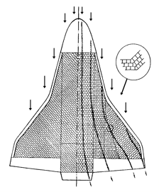
The scheme of tiles’ cutting differs from those applied at Space Shuttle. There are no triangular and acute-angled tiles on BURAN, and all long slots between belts are orthogonal to local streamlines (Fig. 6). The orthogonality of inter-belt slots to the local streamlines promotes a decrease of air column resonant oscillations in inter-tablet zone and, as the corollary, earlier and less probable boundary layer turbulization occurs during the period of maximum heat flows.
|
|
Figure 6. Schemes of tablet cutting on bottom faces of BURAN (right) and those of Space Shuttle (left) |
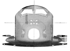
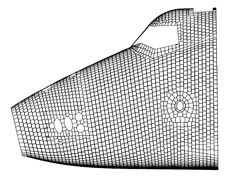
In Figures 7 … 8 the schemes of cutting grids of the Orbiter’s units, formed by means of computer graphics, are shown.
|
|
Figure 7. Cutting of tiles on BURAN (front view) |
|
|
Figure 8. Cutting of tablets on BURAN (side view) |
The fan cutting is applied on the nose part, on elevons and on the fin, which is opposite Space Shuttle.
Pentagonal re-docking tiles are introduced for turning the belt direction, which do not have acute angles in the plan.
All tile’s belts located around units joints, hatches and portholes are compensatory, because they are corrected according to edge zones measurements.
Totally, there are 38,600 tiles cells in the Orbiter’s data base (with engine nacelles), 20% of them are non-regular and 15% are especially complicated, having undercuts, bevels, grooves, holes, flutes, oblique tee-bevels. New relations between firms are built for the first time in domestic practice of engineering, when databases are the basis of an interface between a designer bureau and a plant. The same bases (in their initial theoretical version) have made the general-system core of the process integrating the activities of systems, which traditionally worked separately before – the system groups of CAD and Automated Systems of Control for Technological Processes.
In an outline of databases the units of relational approach towards the work of a informational and reference system are included. Seven percents of databases volume are taken with the multilevel directory oriented to search ‘by tree’ with hierarchical numbering of types of articles, units, zones, belts and elements. Addresses of geometrical and code data arrays are contained in the directory. These arrays are recorded in the main archive with provided updating and archiving of the data volumes. To make the control easier the following main codes are displayed by two decimal numbers: position, chromatics, blanks’ types, materials and manufacturing processes.
The check totals of data arrays and sum of parameters circumscribing lengths of reference normals and surfaces curvature along the base grids of points are used as the control details at all basic operations of data transmission and rewriting.
The information about airframe framework’s panels was transferred to production by computer carriers, using the operations similar to those described above, but without adjusting the forms according to the measurements with the help of overlaying coordinator-graphs. The generalized computer tabular-schematic description on the basic geometrical parameters is stipulated for the standard parts of turning group, components of pipe joints of pneumatic and hydraulic systems. This information was transferred by computer carriers and a set of codes, controlling the tool motion from consoles of semiautomatic machine tools at Experimental Plant of NPO MOLNIYA.
In the problems of tracing and manufacturing electric cable assemblies for BURAN’s bays, the stages of lengths calculations, issue of standard schematic drawings and sheets of furnishing elements are computerized. The general-layout diagrams of bays with different variations of cables laying are processed on the plane tables of graphic information encoding. After selection of the best ways of tracing the standard drawing with set sizes is formed from the initial static database with the specification, allowing for common chests and cable trunks, and nomenclature of standard parts.
Twenty percents of the total industrial documentation on orbital spaceship are transferred without drawings, on computer carriers, and still as much are transferred in drawings, made by means of computer graphics.
The employees of NPO MOLNIYA and adjacent firms are awarded with the Premium of the Council of Ministers of the USSR for creation of unique, the first in Europe process of paperless technology.
Conclusion
Methodology of designing BURAN orbital spaceship, which basis the system approach and through mathematics use in development is put, will undoubtedly find implementation and receive further development at creation of aerospace systems and new samples of aircraft engineering, and in many other branches of economy.