
- Documentation
- Table of contents
- AKC
- Introduction
- Airframe Creation
- Technological Problems
- Experimental plant
- Building plant
- Conf. Development
- Aerodynamic Designing
- Algorithms of control
- Guidance & control
- Stand for training
- Training center
- Horizontal flight tests
- Crew on board
- Auto Landing complex
- Structure
- Payload bay
- Metallic material
- Non metallic material
- Non metallic material
- Cabin assembly
- Thermal designing
- Thermal protection
- Heat protection
- Quartz fibre
- Computer designing
- Gas's dynamic
- Strength
- Basic direction
- Tech. preparation
- Technical diagnostics
- Methods & means
- Radio nav. support
- Information & controls
- Control of onboard equ.
- Electric power dist.
- Electromagnetic
- Antennas installation
- Auxiliary power unit
- Hydraulic system
- Cabin
- Safety
- Air transportation
- Automatic landing
- Exp. working out
- Return to space
- SPIRAL
- Analysis of concept
- Horizontal take-off
- BOR-4 & BOR-5
- MAKS multipurpose
- MAKS-D
- Thermal design
- Gas & thermal design
- Wing deflection
- Flight performance
- Maks structure
- Metal materials
- Advanced non metallic
- Information provision
- Onboard starting comp.
- Onboard control comp.
- Control organization
- Aerospace systems
- Economic investigations
- Triplane aircraft
- Technical inventions
- Scientific potential
- Triumph and tragedy
- Birds of a Feather?
- TsAGI wind tunnel
- Bibliography
| -The Mriya is destroyed. |
| -Shipping of Buran-KS to Sotchi. |
| -Antonov is no more. |
| -Buran is now a museum. |
| -New pictures of the blogger Ralph Mirebs. |
From SPIRAL to MAKS
The MAKS Multipurpose Aerospace System
Skorodelov V.A.
Three version of the MAKS Aerospace System with the AN-225 subsonic Carrier-Plane are considered: with the Orbital Plane (Orbiter) and the External Fuel Tank (MAKS-OS version), the cargo version with the expendable Rocket Stage (MAKS-T version) and the full reusable version (MAKS-M version). The main performance of these versions and the description of the MAKS component elements are presented.
The development of the MAKS aerospace system started when BURAN orbital spaceship was still in creation phase. The major goal of the MAKS project is to reduce essentially the cost of space transportation operations and to increase efficiency of the launch system thanks to the advantages of the mobility launch from subsonic carrier-plane. The MAKS project is based on the results of SPIRAL project, BOR experimental flying vehicles as well as on many other studies performed in accordance with ENERGIA-BURAN program:
- as a prototype of carrier-plane (CP) the An-225 subsonic airplane is used;
- its first task was to transport the BURAN orbital spaceship and component parts of the ENERGIA rocket launcher;
- on the MAKS orbiter the installation of two RD-701 rocket tri-propellant engines based on RD-170 engine from the first stage of ENERGIA rocket launcher is foreseen;
- thermal heat protection and high-temperature constructional materials developed for the BURAN orbiter after some improvement of its characteristics can be used for the MAKS system.
The MAKS system has two stages:
- An-225 carrier plane;
- space stage.
The An-225 carrier plane is a mobile launch platform delivering the space stage to a given starting point. It is also used as a boost stage providing optimal starting conditions for autonomous leg of the space stage injection.
The second space stage has three different versions: MAKS-OS, MAKS-T and MAKS-M.
The MAKS-OS Version with the Orbital Plane and the External Fuel Tank
In this MAKS basic version the second stage (Figure 1) consists of the reusable orbital plane (OP) and expendable external fuel tank (ET).

|
|
Figure 1. The second stage of МАКС-ОS version |
The MAKS-OS version is used for injection into an orbit and recovery to the Earth of small-scale and middle-scale payloads as well as for performing of a wide spectrum of mission at the altitudes from 200 up to1500 km.
The typical flight task of the system is performed in the following way:
1. The carrier plane with the installed second stage takes off from the basing airport and flies to starting point above Earth surface where it must launch the second stage. The launching geographic coordinates and azimuth are determined by required orbit parameters. For the CP flight range up to 1000 km this task is performed by the carrier-plane using its on-board fuel reserves. For longer flight range as well as providing condition to launch the second stage into equatorial orbit this task is carried out with in-flight refueling of the carrier-plane.
2. At the starting point, at approximately 9 km altitude the carrier-plane makes pre-starting pull-up maneuver to provide optimal combination of the initial trajectory parameters for the second stage: flight altitude, velocity and trajectory angle. Carrying out pre-starting maneuver the carrier-plane at first during a shallow descent increases its velocity and then performs pull-up maneuver with increasing trajectory angle and flight altitude. At this leg of flight the main propulsion unit of the second stage is started.
3. When a required trajectory angle is reached, the separation process of carrier-plane and the second stage starts. It consists of two phases:
- quick reduction of normal g-load down to value of ny = - 0,6 g, at this moment breaking of mechanical connections between the carrier-plane and the second stage appears;
- collision-free separation of the carrier-plane and the second stage. During separation the control of both the carrier-plane and the second stage ensures the safe distance between the carrier plane surface and the rocket engine’s jet flow.
5. When the second stage reaches a near orbital velocity, the main propulsion unit cuts off, the external fuel tank separates from the orbital plane, descends, enters into the atmosphere dense layers and burns there. The injection trajectory is chosen so that unburned pieces of the fuel tank fall into the ocean.
6. The orbital plane after separation from the fuel tank starts the orbital maneuvering engines, achieves the operational orbit and performs the major task of orbital flight.
7. When the task is completed the orbital plane fulfils a de-orbit retro maneuver by means of the orbital maneuvering engines, enters into the atmosphere and fulfils the atmospheric controlled descent and landing on the base airport.
The main propulsion unit of the second stage consists of two RD-701 tri-propellant engine produced by NPO ENERGOMASH. They use the following fuel components: liquid hydrogen, liquid oxygen and kerosene. The RD-701 engine has two modes if consider used fuel and nominal power:
- the First mode: hydrogen-oxygen-kerosene fuel, thrust in a vacuum - 200 tons, specific impulse - 415 s;
- the Second mode: hydrogen-oxygen fuel, thrust in a vacuum - 80 tons, specific impulse - 460 s.
The main engines are installed on the orbital plane and belong to reusable elements of the MAKS system. The efficiency of using the RD-701 engine in the MAKS system and other RSTS is shown in the paper: Analysis of Various Concepts of the Reusable Space Transportation Systems.
The fuel for the main propulsion unit is located in the external fuel tank and is supplied into the main engines through plug-type connection. The external fuel tank consists of three separate tanks: in the front part – liquid hydrogen tank, in the middle – liquid oxygen tank and in the rear part – kerosene tank. The external fuel tank is fixed on the orbital plane by three powerful connector assemblies with the pyrotechnic separation mechanism.
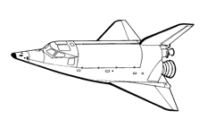
The MAKS orbital plane (Figure 2) also has the Orbital Maneuvering System (OMS) used for orbital flight and during the beginning of the descend in the top atmospheric layers. The Orbital Maneuvering System consists of two liquid orbital maneuvering engine and three engine units (nose, left and right at the rear) of the Reaction Control System (RCS).
Two OMS engines of 3000 kg thrust each are used for the elliptic ascent, orbital transfers and breaking before descent.

|
|
Figure 2. The MAKS orbital plane |
RCS includes 28 small liquid engines with 2,5 and 40 kg thrust which provide angular control of the orbital plane relatively to center of gravity and the plane-parallel motion during the mooring-and-docking maneuvers in orbit.
All RCS engines use pollution-free fuel: hydrogen peroxide and kerosene.
To control the atmospheric flight the orbital plane has the aerodynamic control surfaces: elevons, flap and the rudder combined with air break.
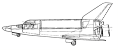
The payload bay (PLB) with folds is located in the middle part of the orbital plane. The folds are opened up during the flight in orbit. The injected and recovered payloads are placed in this payload bay. The basic manned version of the orbital plane (Figure 3) has a cockpit for two-pilot crew. The main overall dimensions of the orbital plane: length – 19,3 meters, wingspan – 12,5 meters, height – 8,6 meters.

|
|
Figure 3. The basic manned orbiter version |
There are some another versions of the orbital plane for different tasks:
- unmanned orbiter (Figure 4) for injection of payloads heavier than those for manned version and for prolonged orbital flights including flights at high altitudes;
- orbiter’s version for Transport Maintenance Service (TMS) of the orbital stations and unmanned platforms as well as for emergency crew rescue from the space objects.

|
|
Figure 4. The unmanned orbital plane |
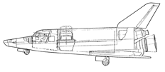
There are two orbiter’s version for the TMS missions. TMS-1 is used for transportation of relief crews and payloads into internal modules of the orbital stations. They are transported in the pressurized module of the orbital plane. To perform such actions payload bay are equipped with a docking unit and the second pressurized cabin (Figure 5).

|
|
Figure 5. The orbital plane TMS-1 |
Orbiter for emergency crew rescue of space objects has a similar layout. Some differences are displayed in enlarged fuel reserves for higher maneuverability in orbit.
TSM-2 version is used for supplying of payloads – equipment and assemblies installed on the outer surface of the space station (solar batteries, antennas and other) – in non-pressurized cabin. It also can be used for supplying fuel components and other liquids in tanks placed in non-pressurized payload bay (Figure 6).

|
|
Figure 6. The TMS-2 orbital spaceship |
Using various equipment located in the payload bay the shown concept of orbital spaceship allows to solve a wide range of missions.
The MAKS-T Version with an Expandable Launch Unit for Injection Heavy Payloads
This version of the system (Figure 7) with an expandable space stage is used for injecting heavy payloads with weight up to 18 tons.
The second stage is composed of some MAKS general elements: the external fuel tank, the main propulsion unit, the mechanical and communication assemblies with carrier-plane and a part of the on-board control system. The payload with a cowling is placed onto the external fuel tank instead of the orbital plane (Figure 7).

|
|
Figure 7. The MAKS-T second stage |
The MAKS-M with Completely Reusable Space Stage
The second stage in this system version (Figure 8) presents a full reusable unmanned space vehicle used for injection of payload into low earth orbit and its recovery to the Earth.
The fuel tanks of main propulsion unit are built-up into construction of reusable orbital spaceship. The payload bay is placed between fuel tanks. Their overall dimensions are less then in the basic version of the orbital plane MAKS-OS.

|
|
Figure 8. The MAKS-M version |
The second stage of the MAKS-M version (Figure 9) consists of blocks unified with MAKS-OS version:
- main propulsion unit;
- orbital maneuvering system;
- fuel tanks fittings;
- on-board control system;
- power supply system;
- temperature control system;
- part of steering drives and other.

|
|
Figure 9. The MAKS-M second stage |
The creation of the full reusable MAKS-M system in the presence of the existing technologies looks quite problematic. To provide the injection of the 5..7 tons payload it is demanded to develop new constructional materials and first of all – thermoplastic on the basis of carbon fiber for production of fuel tanks. It is needed to solve one more scientific and technical problem – the creation of integral fuel tanks form the outlines of the orbital spaceship and have a combined covering, included reusable cryogen heat insulation and reusable high-temperature heat protection.
The MAKS-M is considered as possible study direction of conception development of the Multipurpose Aerospace System after MAKS-OS and MAKS-T creation.
The following order of MAKS version creation is foreseen (it is determined by the complexity of solvable scientific and technical problems): MAKS-T, MAKS-OS and MAKS-M. They will be placed in operation according with their creation. They will be able to use the same carrier-plane and the ground-based infrastructure. Each version is used for performing one task range where it is used with maximum efficiency.
The MAKS-OS and MAKS-T versions and later MAKS-M version if exploited in common can perform wide range of missions, including:
- injection payloads into an orbit and their recovery;
- transport service maintenance of the space stations and platforms;
- emergency crew rescue from any orbital objects;
- scientific and technical experiments works in the orbit;
- international control of space usage;
- remote Earth sensing or probing;
- space cleaning against technological pollution;
- in-orbit assembling of large objects from modules injected separately.
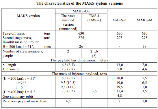
The comparative characteristics of three MAKS system versions are shown in the following table.
Such multipurpose application results in a high intensity of launchings and corresponding operational cost per one launch decreasing for the same carrier-plane, ground infrastructure and control complex.
The MAKS system in comparison with the existing and developed launch systems has several advantages:
- low cost of payloads injection into an orbit;
- multipurpose application;
- possibility of a direct injection of objects into an orbit with any inclination and for a wide range of altitudes;
- operational efficiency;
- a possibility of landing on the airdrome placed at considerable distance from orbital plane;
- possibility of payloads recovery;
- pollution-free application (absence of alienated fields on the ground , non-toxic fuel, low acoustic impact of LR engines on the Earth surface).
The direct injection into an orbit of any inclination and operational efficiency are the principal advantages of the system with mobile launching from airplane in comparison with the vertical take-off launch systems.
A high reusability factor for the MAKS components, multipurpose application and high level of the second stages’ unification, while the ground infrastructure and the first stage are stayed the same, allow to decrease considerably transportation costs for payloads injection into an orbit.

|