

- Documentation
- Table of contents
- AKC
- Introduction
- Airframe Creation
- Technological Problems
- Experimental plant
- Building plant
- Conf. Development
- Aerodynamic Designing
- Algorithms of control
- Guidance & control
- Stand for training
- Training center
- Horizontal flight tests
- Crew on board
- Auto Landing complex
- Structure
- Payload bay
- Metallic material
- Non metallic material
- Non metallic material
- Cabin assembly
- Thermal designing
- Thermal protection
- Heat protection
- Quartz fibre
- Computer designing
- Gas's dynamic
- Strength
- Basic direction
- Tech. preparation
- Technical diagnostics
- Methods & means
- Radio nav. support
- Information & controls
- Control of onboard equ.
- Electric power dist.
- Electromagnetic
- Antennas installation
- Auxiliary power unit
- Hydraulic system
- Cabin
- Safety
- Air transportation
- Automatic landing
- Exp. working out
- Return to space
- SPIRAL
- Analysis of concept
- Horizontal take-off
- BOR-4 & BOR-5
- MAKS multipurpose
- MAKS-D
- Thermal design
- Gas & thermal design
- Wing deflection
- Flight performance
- Maks structure
- Metal materials
- Advanced non metallic
- Information provision
- Onboard starting comp.
- Onboard control comp.
- Control organization
- Aerospace systems
- Economic investigations
- Triplane aircraft
- Technical inventions
- Scientific potential
- Triumph and tragedy
- Birds of a Feather?
- TsAGI wind tunnel
- Bibliography
| -The Mriya is destroyed. |
| -Shipping of Buran-KS to Sotchi. |
| -Antonov is no more. |
| -Buran is now a museum. |
| -New pictures of the blogger Ralph Mirebs. |
BURAN Orbital
Spaceship Airframe
Creation
Control of Onboard Complex of Equipment
Karimov A.G.
The main problems of creation the systems of monitoring and control for the onboard equipment complex of BURAN Orbiter and its program software (Software) are explained. The structure of the control system (CS) is presented. The problem of Software structure synthesis with sectioning it into independent standard units is considered. An effective automated way of CS Software working-out on Full Scale Stand of Equipment (FSSE) is considered, including simulation of abnormal situations in onboard systems and their communication channels.
In the process of BURAN Orbiter creation, the responsible developers (NPO ENERGIA, NPO AP and NPO MOLNIYA) solved a complex technological task of automatic monitoring and control of the onboard complex of the Orbiter’s equipment at all stages of its operation (preparation for launch, flight and landing). The novelty and non-standard approach to the solution of this problem were basically determined by:
- essential differences of Orbiter’s operational conditions as compared to conventional airplanes;
- complexity and heterogeneity of the onboard systems (OBS) structure;
- strong requirements to reliability of monitoring and control equipment and its software;
- necessity of precise organizational and technical work coordination for a large number of OBS developing enterprises with the purpose of creation the integrated (inter-correlated) hardware-software complex in view of solving the problem of Orbiter control.
The control system (CS) for the onboard complex of the equipment should primarily ensure the reliable control and diagnostics on the Orbiter’s state. This task is divided into three independent directions:
- control of crew state;
- control of construction state;
- control and diagnostics of the OBS operational state.
Practical implementation each of these directions was provided at different stages of Orbiter’s creation depending on the program of unmanned and manned launches. During the Orbiter’s first unmanned launch the most complicated problem of automatic monitoring and control of onboard complex of equipment was decided, mostly with the purpose of successful flight accomplishment and, which was the main, reliable automatic landing at the final stage.
Under such conditions, the most complete technical implementation was obtained for the CS and Software structure. This structure has provided the reliable solution for the functional monitoring and diagnostics of OBS working capacity and formation on this basis (in view of the mission plan) control actions on switching OBS operational modes, failures blocking and, if necessary, re-structuring hardware and software of Orbiter’s equipment.
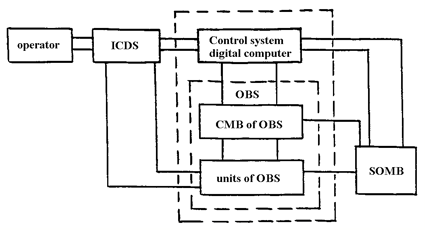
The synthesized generalized CS structure and its connections with OBS are displayed in Figure 1. The structure is built with allowance for three possible Orbiter’s control modes: automatic, manual and under commands from the ground-based control complex (GBCC). The formation of control actions is made on the basis of two-level usage of the monitoring and diagnostics system:
1. Level of a built-in monitoring inside every OBS executed by control and monitoring blocks (CMB) of OBS. The CMB provide state monitoring of the functionally closed OBS and make blocking at detection of failures by means of switching to standby (reserving) channels.
2. Level of computerized monitoring and diagnostics and implementation on this basis of control functions taking into account plan of mission. Collection of monitoring and diagnostic information in a necessary volume in CS was provided with the help of Orbiter’s system of onboard measurements (SOBM).
|
|
Figure 1. Structurally functional scheme of Orbiter’s equipment construction |
The main problem of functional systems of control and diagnostics (SCD) in the mode of automatic flight was a reliable detection of failures of OBS with the help of built-in OBS monitoring aids and CS centralized computing means (onboard digital computer of control system DC CS, Figure 1). Usually, the generalized signals and indexes from CMB were used for monitoring the state of OBS by CS. In case of necessity of more complete monitoring of separate OBS, the information from SOBM was used.
Conducted by specialists from NPO MOLNIYA analysis on the problems and communications of ‘aircraft’ OBS has allowed to arrange rationally the tasks on the mentioned levels, simplify communications of OBS with CS, which improved reliability of solving control problems. ‘Aircraft’ systems are understood as systems designed for BURAN Orbiter by enterprises of aircraft industry at the technical direction of NPO MOLNIYA.
For manned flights, the possibility of OBS manual control with display of information coming from CS by means information and controls display system (ICDS) was provided.
The problem of Software development becomes complicated in the centralized computing structures of CS. The volumes of software are sharply increasing. The tasks are diverse by functions and types of calculations, requirements on reliability and accuracy of solution are various, carrying out software adjusting in separate units requires checkouts of the whole bulk of Software, etc. It was a disadvantage of the synthesized CS structure, however practically no technical possibilities to construct more flexible decentralized structures with developed service software were available at the time of BURAN Orbiter development startup.
Nevertheless, the experience of creation and improvement of the considered BURAN Orbiter CS with Software should be used at creation of advanced space vehicles with other arrangements of onboard equipment structures that would result in reduction of terms and costs of their designing.
With the purpose of particular simplification of Software of the CS centralized computing means development and improvement, specialists from NPO MOLNIYA have performed a synthesis of standard units with minimum interconnections within the Software structure. Besides, the tasks were rationally split over the means of CS and OBS with maintenance of their maximum independence and minimum of interconnections between them.
The synthesis of standard Software structures was conducted in two directions: structural and parametric.
|
During structural synthesis the following were determined:
- tasks and structure of Orbiter Software algorithms;
- standard units of algorithms according to the principle of maximum autonomy.
During parametric synthesis the following were accomplished:
- determination of volumes of information interconnections between separate units of Software CS standard algorithms and connections between CS and OBS equipment;
- analysis on characteristics of information flows at development the Software standard units, CS and OBS equipment and acceptance of solutions on forming channels of interconnections between OBS and CS on this basis, organizing their backup and choosing Software structure.
The Software synthesis has determined maximally independent standard units in the structure of control algorithms:
- of top level intended for determining the conditions of start and formation of indications for algorithms of OBS switching into the required operational modes;
- of OBS switching into a new operational mode and termination of the before triggered mode;
- choice of control operations, etc.
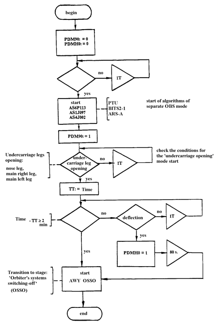
The structure of a standard top level algorithm is displayed in Figure 2.
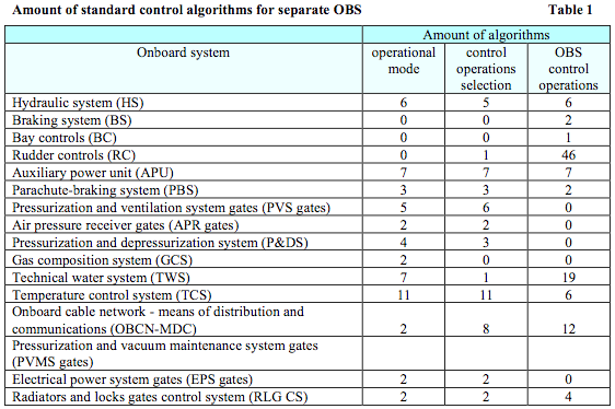
The algorithm provides OBS actuation and transfer to the required operational modes at the descent phase (90…0 km). In particular, formation of indications required for starting algorithms of information collection system, system of undercarriage release, parachute-braking system, etc. The structure of systems, types and amount of algorithms designed by NPO MOLNIYA are displayed in Table 1.
It is necessary to note that the control algorithms of a number of onboard ‘aircraft’ systems of essential novelty were created in the process of the work. The majority of control algorithms were implemented as electronic circuits and protected by copyright certificates. On the basis of the accomplished synthesis, specialists of NPO MOLNIYA, with active participation of specialists of allied enterprises, have developed technical specifications (TS) on OBS and their computing means, which have allowed to ensure a rational integration of CS and OBS means.
|
|
Figure 2. Standard algorithm for the stage of descent |

|
|
Figure 3. Standard monitoring matrix of technical state for one of three HS (HS3) channels |
Synthesis of the tasks on SCD OBS algorithms, their interaction with control algorithms (CA) of OBS analysis showed that construction of some other structures of algorithms is expedient for the tasks of control and diagnostics. The SCD algorithms are connected (during unmanned flight of Orbiter) to operation automatically according the appropriate indications formed in CA, or regularly through the set of time periods. During the manned flight, the crew can work with the CS Software in interactive mode with the help of a multifunctional control panel (MFCP).
In both cases the SCD algorithms form necessary signals, messages and texts (and also indications of failures registered in automatic CA) in ICDS under the priority scheme for operating decision making on control either with or without participation of the crew. In connection with a large volume of information messages, it is expedient to use monitors of a television type in ICDS, messages on which are given in a form convenient for perception (texts, mnemonic diagrams, tables, etc.).
As against CA OBS, the SCD algorithms, operating with large volumes of continuous parameters and also forming considerable volumes of messages about abnormal situations, need to be implemented in a form of stored in CS computer monitoring matrices. In this case the volumes of memory required for computing means are reduced, control Software adjustment becomes easier.
The monitoring matrixes are the tables in which the information on inspected parameters and OBS technical condition is written in compliance with the definite rules. The columns of monitoring matrixes correspond to the object (OBS) parameters. The matrixes’ rows – to the OBS conditions (‘norm’ or different kinds of ‘failures’).
This or that condition is considered implemented at detection of the inspected parameters in particular intervals, which numbers are indicated in the matrix of condition in interception of columns and rows. Either signal parameters values (1 or 0), or numbers of intervals of parameters splitting (2, 3, etc.) are the elements of matrix. The combination of parameters’ values in the matrix row characterizes the situation corresponding to this row.
In Figure 3 the monitoring matrix of one of the hydraulic system channels is displayed as an example. In four columns of the left part of the matrix the following are shown:
- N is row number of the matrix;
- P are identifiers of parameters and values, which are assigned to them at implementation of the appropriate row;
- M is the address of transfer to the analysis of another matrix or of a certain row of this matrix (Mk means the end of processing);
- Q is indication of the message, which is mapped on display device.
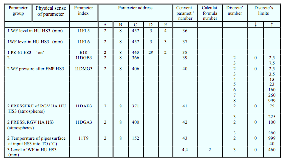
The columns in the right part of matrix correspond to the inspected parameters, which numbers are indicated above each of the columns and which (except for the last) are shown in the file of parameters of technical condition of a three-channel hydraulic system (HS3). The last column characterizes parameter P, shaped according to column Р of the matrix.
|
|
Figure 4. File of technical state parameters of HS3: |
WF - working fluid; HU - hydro-unit; PS - pump station; FPM - fluid preparation module; HA - hydraulic accumulator
The monitoring matrixes’ processing is carried out with the help of a versatile algorithm determining the order of analysis. The processing starts at appearance of a request, which is formed by CA OBS or regularly at the set intervals.
The matrix analysis consists in row by row matrix elements comparing with the measured values of OBS parameters. At that OBS parameters are understood as both the primary parameters obtained from SOBM, and the secondary, which values are either calculated using the special subroutines on primary parameters, or are formed in control algorithms CA (indications, signals). At concurrence of the measured values of parameters with those recorded in one of the row of matrix the conclusion is made on the current condition of OBS corresponding to this row, and the appropriate indication is formed.
Each of indications formed by system of control and diagnostics, is followed by an appropriate text message, which is automatically highlighted on a screen of the multifunction indicator. All messages are assign their own priority, and when several messages are simultaneously under formation, the one of primary priority is imaged on the screen.
The remaining messages form a priority queue and are called by operator as required. The messages can contain a brief characteristic of an abnormal situation and guidelines on operator’s actions.
Either values (0 or 1) of signal parameters, or numbers (2, 3, etc.) of discrete values of intervals of splitting of analogue parameters are indicated in the points of rows and columns interception in the right part of matrix.
The empty element in the right part of matrix means that the condition of OBS corresponding to this element does not depend on parameter value, in which column this element is placed. The first three row of matrix correspond to ‘norm’ HS3 in different operational modes, rows from 4th to 20th – presence of faults and failures in HS3. The last row of matrix characterizes an ‘unforeseen’ situation, i.e. such condition of HS3, which are not shown in the matrix in view of small probability of their occurrence, for example, an event of several failures simultaneously.
|
|
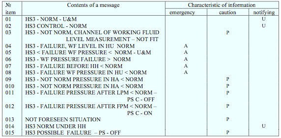
Figure 5. File of messages about HS3: |
C – controls; HA – hydro-accumulator; HH – hydraulic heating; HU – hydraulic unit; A – emergency; P – caution; U – notifying; U&M – notifying and message; WF – working fluid; PS – pump station;
In the file of parameters (Figure 4) each HS parameter has its group (1 – signal, 2 – analogue, 3 – calculated under the formula). Every parameter is distinguished by its physical sense and has index (telemetry index or identifier in the onboard digital computer). It has also an address in telemetric system (A – number of a complete set of TM system, B – number of plate of collecting messages, C – channel number, D – number of a word in TM array, E – number of category in a word). Every parameter has its own number. The analogue parameters have a number of discrete with indicating interval limits. Parameters from the third group have also a number of calculating formula.
The texts of the messages displayed on the screen at implementation of this or that row of matrix with indication of their priorities (emergency – A, preventing – P, informing – U) are shown in Figure 5.
For more detailed analysis of OBS technical condition, operator has a possibility to call, besides the messages, additional information as frames of control-diagnostic information (CDI) display. The frames display the information either in the form of tables indicating OBS functional parts and their condition (norm, failure), or as mnemonic diagrams with the indication of condition of OBS elements, scales values of parameters with the indicating tolerances, etc.
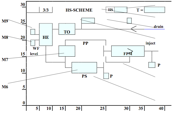
The MFCP operator calls the frames by use of their number. At that, the algorithm of displaying forms the appropriate frame using its encoded and stored in the CS computer’s (or in CS recorder). The algorithm makes also the inquiry of necessary parameters from the system of onboard measurements (SOBM), indications formed in CA, and situations indications from monitoring matrices for dynamic information’s displaying in the frame. The description and type of the CDI frame on HS3 are shown in Figures 6 and 7.
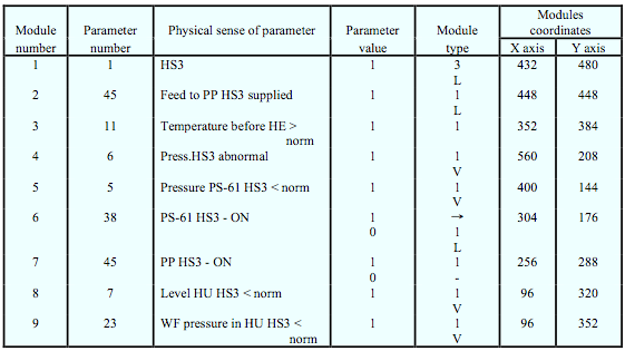
On the frame (Figure 6) static, invariable in time part of frame – mnemonics of HS3 are shown with indication of locations (M1…M9) dynamic, changeable in time and dependent on values of inspected parameters of modules (fragments of images).
In the description of a frame, every module is put in conformity with the value of one of inspected parameters registered in the file: parameter N. 38 with an index E18 corresponds to module M6. Mnemonic symbol of ‘→’ is displayed in the module at parameter value equal to 1, and mnemonic symbol ‘V’ - at zero value. The X0, Y0 coordinates of the modules’ position on a screen are indicated in the description of the frame.
|
|
Figure 6. Description of CDI frame of HS3: |
PP – pressurizing pump, HE – heat exchanger
The explained information illustrates in a rather complete volume the contents of work and materials for CDI algorithms. It is necessary to remember that at designing the display as a mnemonic diagram, the appropriate ergonomic estimation of indication types on ECU should be conducted.
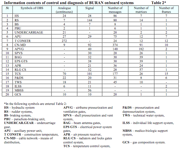
The work was accomplished on creation of CDI algorithms for every ‘aircraft’ system of Orbiter. In Table 2, the information contents used for monitoring and diagnosing separate OBS, and amount of technical condition monitoring matrices of systems are displayed.
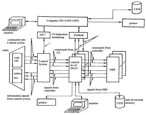
For the CS and its Software qualitative improvement, specialists of NPO MOLNIYA have accomplished a large work (together with NPO AP and NPO ENERGIA) on creation of stand base and technology of working-out. Without detail reviewing, it is still expedient to note the developed by specialists from NPO MOLNIYA, together with Kiev Polytechnic Institute, a special automated hardware-software director logic checkout complex (DLCC) was implemented in the full-scale stand of equipment (FSSE). This was done with the purpose to increase the efficiency of working-out the connections between CS and OBS and CS Software. The scheme of connections of DLCC means with FSSE equipment is displayed in Figure 8.
The automated complex of Software working-out includes:
- the Orbiter’s control system;
- onboard systems or their simulators;
- controls and indicators of CS information;
-
director logic checkout complex (DLCC-CS Software), including:
- special controllers,
- adapter of direct access (AD-7) to CS memory,
- jumper means.
The automated complex provided:
- automated checkout of CS software in a part of OBS control;
- formation of input test actions in CS;
- simulation of CS and OBS operation (in case of their unavailability or absence in the structure);
- registration of outcomes of working-out.
The peripheral memory means of high capacity provided storage of verifying test cycle patterns compiled on a designed special-purpose high-level Dialogue-P language, and displays supported the dialog mode of operators’ work with the system.
|
|
Figure 7. Frame of CDI of HS display (mnemonic diagram): |
The DLCC controller has provided the control and change on logical values of signals and commands (the signals are from OBS and commands are from CS). The DLCC has also provided interlock of signals and commands.
Using DLCC on FSSE stand allowed to carry out an automated checkout of CS Software in abnormal situations (simulation of breaks, information distortion, etc.) over all branches of the algorithms. The operative elimination of detected errors with the subsequent full-scale Software checkout at all stages of tests was provided in the system of working-out. With this purpose a wide-range complex of technological programs ensuring organization of tests, formation of OBS operation models, measuring means error detection and archiving, necessary test data processing, localization and operative elimination of errors in the Software, organization of re-testing, etc. was developed.
The team from Kiev Polytechnic Institute has taken a large part in creation of the system of onboard Software working-out.
Joint work of NPO MOLNIYA and one of the departments of this institute ‘Development and implementation of algorithms and software for problem solving of stand CS and onboard equipment of a flight vehicle working-out’ was awarded with the State Premium of Ukraine in 1987. Specialists of NPO MOLNIYA G.P.Dementiev, A.G.Karimov, V.T.Pereverzev and V.S.Fedorov were nominated the laureates of the State Premium of Ukraine. Many specialists of NPO MOLNIYA participated in the works of creation of the complex of onboard equipment CS and CS Software including: Mr. Kolobov V.A., Novikov A.D., Kravchenko V.V., Timoshik S.Ya., Gordiyko S.V. and Glazunov A.Ye.
The final monitoring tests of CS and it Software were conducted on the complex stand of NPO ENERGIA in a full complete set of nominal equipment and instrumentation and at realization of checkouts on the nominal Orbiter during its preparation for launch.
|
The results of complex tests in these positions confirmed high efficiency of working-out accomplished with CS and Software on the complex FSSE stand with DLCC and other means of experimental tests of NPO MOLNIYA.
Conclusion
1. The essential differences of conditions of BURAN Orbiter’s operation from those of aircraft, rigid requirements on OBS reliability, complexity and heterogeneity, etc. have predetermined the application of new approaches and nonstandard engineering solutions at creation of the integrated structure of the OBS control system (OBSCS). This system has provided a reliable control and monitoring of operation capacity of BURAN Orbiter at all stages of operation (preparation for launch, flight and landing).
2. The immanent disadvantages of the centralized computing structures on implementation and working-out of Software were to a certain extent reduced by rational distribution of tasks between CS computing means and blocks of OBS control and monitoring, and structure Software display as a maximum independent units of algorithms.
3. Using the effective complex of director logic checkout in the structure of a FSSE stand with simulation of a number of different situations in OBS has provided a reliable OBSCS and it Software working out.
4. The analysis and generalization of experience of Orbiter CS development create real premises for development of more high-quality technologies of designing advanced aerospace transport systems (ASTS) due to:
|
|
Figure 8. Automated complex for check and working out the OBS control Software (NPO MOLNIYA) |
- CS flexible decentralized structures with registration of considerably increased capabilities of onboard and terrestrial computing means;
- efficient mathematical complexes (stands) with advanced simulation of ASTS problems;
- applications of universal stands for working-out functional OBS and Software units;
- full automation of Software working-out processes, etc.
5. The experience of CSOBS Orbiter integrated structure creation displays the necessity of ASTS equipment integration on higher levels – those of onboard control complexes (OBCC), which in aggregate solve the problems of control of ASTS mission and OBS operation, monitoring and diagnostics.