

- Documentation
- Table of contents
- AKC
- Introduction
- Airframe Creation
- Technological Problems
- Experimental plant
- Building plant
- Conf. Development
- Aerodynamic Designing
- Algorithms of control
- Guidance & control
- Stand for training
- Training center
- Horizontal flight tests
- Crew on board
- Auto Landing complex
- Structure
- Payload bay
- Metallic material
- Non metallic material
- Non metallic material
- Cabin assembly
- Thermal designing
- Thermal protection
- Heat protection
- Quartz fibre
- Computer designing
- Gas's dynamic
- Strength
- Basic direction
- Tech. preparation
- Technical diagnostics
- Methods & means
- Radio nav. support
- Information & controls
- Control of onboard equ.
- Electric power dist.
- Electromagnetic
- Antennas installation
- Auxiliary power unit
- Hydraulic system
- Cabin
- Safety
- Air transportation
- Automatic landing
- Exp. working out
- Return to space
- SPIRAL
- Analysis of concept
- Horizontal take-off
- BOR-4 & BOR-5
- MAKS multipurpose
- MAKS-D
- Thermal design
- Gas & thermal design
- Wing deflection
- Flight performance
- Maks structure
- Metal materials
- Advanced non metallic
- Information provision
- Onboard starting comp.
- Onboard control comp.
- Control organization
- Aerospace systems
- Economic investigations
- Triplane aircraft
- Technical inventions
- Scientific potential
- Triumph and tragedy
- Birds of a Feather?
- TsAGI wind tunnel
- Bibliography
| -The Mriya is destroyed. |
| -Shipping of Buran-KS to Sotchi. |
| -Antonov is no more. |
| -Buran is now a museum. |
| -New pictures of the blogger Ralph Mirebs. |
From SPIRAL to MAKS
The MAKS Flight Performance
Dr. Dudar E.N., Lobzova T.A.
The flight trajectory, resulted from mathematical modeling, for the MAKS Aerospace Complex on following legs are indicated: flight of the Carrier-Plane to the Start-up region, Pull-up maneuver, Separation of the Second stage and its Injection into the Earth orbit, Descent of the Orbital Plane (Orbiter) in the atmosphere. The effect of some design parameters and parameters of the orbit on the flight performance of ascent for three MAKS versions are shown: MAKS-OS, MAKS-T and MAKS-M. It is done analysis of the main features of flight dynamics of these versions. The ways of the flight performance improvement are indicated.
The main element of the Multipurpose Aerospace System (MAKS) is Aerospace Complex (ASC), which represents a compound flying vehicle (FV), consisted of AN-225 subsonic Carrier-Plane (CP) and the second space stage with liquid rocket engines (LRE).
The system has three versions of the second stage:
- OPT - orbital plane with a tank – manned or unmanned orbital plane (OP, Orbiter) with an external fuel tank (ET) – the MAKS-OS version;
- LU – expandable launch unit consisted of a transport module (TM) with a space module (SM – space tug and satellite), placed on the top – the MAKS-T cargo version;
- OP – orbital plane with build-up fuel tanks – completely reusable MAKS-M version.
All three versions are equipped with a standardized main propulsion unit placed on the second stage and consisted of two RD-701 tri-propellant dual-mode engines. The main propulsion unit is placed on the reusable Orbiter (MAKS-OS and MAKS-M) or in the rear part of an expandable transport unit (MAKS-T).
Through (end-to-end) flight trajectory of the aerospace complex and its elements contains ‘completely airplane’ and ‘rocket’ legs, a leg of the orbital flight, as well as ‘glider’ leg when descending through atmosphere and non-powered horizontal landing on runway.
Three versions of the second stage and corresponding versions of the aerospace complex differ in aerodynamic as well as takeoff and landing performance. Flight schemes of these versions also differ at various legs, for example, MAKS-OS, MAKS-T and MAKS-M systems have different schemes of elliptical assent into a circular orbit.
The researches on dynamics of MAKS elements (ASC, OPT, OP, ET, LU, TM and SM) are performed on different mathematical models. These models include the following data bases: aerodynamic characteristics, masses and mass-inertia data, position of gravity center data - for all the MAKS elements. Additionally, data bases with characteristics of the following element are taking into account: carrier-plane’s turbo-jets, main rocket propulsion unit of the second stage, the Orbital Maneuvering System (OMS) engines and the Reaction Control System (RCS) engines of the Orbiter or Space Module. Depending on the aims of researches and the flight legs, different mathematical models of flying vehicle motion are used:
- gravity center motion (trajectory) model;
- gravity center motion model with consideration of balancing deflections of the aerodynamic control devices and (or) the main propulsion units;
- gravity center motion model with consideration of actions, made by guidance and navigation systems;
- full motion model including consideration of angular motions around gravity center, stabilization loop algorithms providing maintenance of the stability and controllability and actuator dynamics. The major flight legs distinguished by motion models used: take-off of the aerospace complex (ASC) from the basing airdrome, the carrier-plane landing after return;
- flight of the aerospace system to the start-up region, the carrier-plane return;
- pull-up maneuver of the ASC before the launching of the second stage, the carrier-plane maneuver for horizontal flight;
- separation of the carrier-plane and the second stage;
- injection of the second stage into an elliptical transfer orbit;
- elliptical ascent of orbiter or space module into a circular orbit;
- orbiter’s de-orbit after orbital flight;
- orbital flight of the orbiter or space module;
- descent of the orbiter in the atmosphere;
- pre-landing maneuver, approach and landing of the orbiter on a runway.
Let’s consider the most important flight legs of the MAKS system.
Flight to the Start-up Region
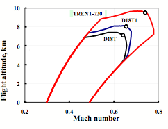
To plot optimal graph of ASC flight to the start-up region at maximum distance from basing airdrome firstly it is necessary to determine equilibrium flight area (EFA) by means of well known Method of Thrusts, suggested by Prof. Zhukovsky N.E. [1]. The EFA boundaries are calculated considering the plane of parameters: Mach number (M), flight altitude (H). At the point of these boundaries a condition of equilibrium (constant speed and trajectory inclination angle) or a condition of flight at maximum permissible values of limiting parameters (lift coefficient, dynamic pressure or Mach number) are held true.
The form and size of equilibrium flight area (maximum Mach number – Mmax, maximum flight altitude, ceiling, – Hmax and other) depend on the ASC mass and its aerodynamic characteristics determined by the second stage. They also depend on a turbojet type used in the carrier-plane.
Figure 1 shows equilibrium flight area for cruising flight leg of the ASS-OS near launching point for three different turbojets of the carrier-plane: domestic D18T turbojets, their advanced version D18T1 and TRENT-720 turbojets, produced in the West Europe and developed by Rolls-Roy company.
|
|
Figure 1. Equilibrium flight area of the ASC-OS aerospace complex |
At the boundaries of the equilibrium flight area points with minimum fuel consumption per kilometer (Ckm min) of the carrier-plane’s turbojets are indicated. These results were received at maximum take-off masses: the ASS - 630 tons and the second stage - 275 tons.
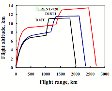
The typical graph of ASC flight to the region, where the second stage start takes place, includes climb legs with a constant dynamic pressure and cruising flight with minimal fuel rate. The dynamic pressure at climbing as well as flight altitude and Mach number at the beginning and the end of cruising flight corresponds to the optimal point Сkm, placed on the boundaries of the equilibrium flight area.
Due to the equilibrium flight area expansion when fuel from carrier-plane tanks is worked out the optimal cruising flight is passing with slight climbing.
When the second stage separates, the ASC mass is sufficiently decreased and optimal flight of the carrier-plane to the basing airdrome passes at the higher altitude and higher speed. The parameters of the CP cruising return flight are optimized in accordance with the scheme used for the ASC flight to the start-up region.
At the airdrome neighborhood the carrier-plane is descending at a certain trajectory inclination angle and reduced thrust of the jets.
The typical profiles of the ASC and CP flight at a longitudinal plane of trajectory for different turbojets are shown in Figure 2.
|
|
Figure 2. Optimal flight profiles for ASC-OS |
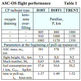
The flight range of the ASC to the start-up region, being equal to return range of the carrier-plane to the basing airdrome (or half of a total distance in a longitudinal plane of trajectory), characterizes system range and is called Parallax. Parallax value (P) – one of the most important characteristic of the aerospace system – should be calculated with consideration of possible abnormal situations, that lead to probable failures at launching and causes stop separation. In such situations return flight to the basing airdrome will pass with higher ASC mass (including second stage) and therefore with higher fuel consumption rate. That’s why maximum permissible distance to the launch point is reduced and at normal flight carrier-plane returns with additional fuel reserves aboard.
To reduce parallax losses and maintain safe landing of the ASC of the MAKS system in abnormal situations a draining the oxidant into atmosphere from the second stage tank are foreseen (approximately 196 tons of liquid oxygen).
When a tri-propellant (kerosene + liquid hydrogen + liquid oxygen) propulsion unit had been taken for the MAKS second stage, a possibility to improve the ASC flight performance had appeared. This may by done by overfilling into the carrier-plane the kerosene, that is used by the second stage propulsion unit at its first mode of operation. Such technical decision (in addition to oxygen draining) leads to increase in total flight range by 500 km as a result of additional kerosene reserve application to the carrier-plane turbojets when separation and launching are stopped.
Table 1 shows parallax (P) values for the MAKS-OS version at different types of the ASC abnormal return:
- without oxygen draining into atmosphere and without kerosene overfilling into the carrier-plane;
- with oxygen draining into atmosphere and without kerosene overfilling into the carrier-plane;
- with oxygen draining into atmosphere and with kerosene overfilling into the carrier-plane.
The table also presents the following trajectory parameters at the beginning of pull-up maneuver: the ASC mass (m0), flight altitude (Н0), Mach number (М0), fuel consumption per 1 km (Сkm), flight time to the start-up region (ts). These optimal trajectory data are calculated for the third designed case with kerosene refilling (flight profiles corresponding to this scheme are shown on figure 2).
|
Nowadays the basic version of the MAKS project is considered to include the carrier-plane engines D18T1 and oxygen draining into atmosphere without kerosene refilling in abnormal situations.
As Table 1 shows, considerable improvements of flight performance will be achieved if more economical and powerful turbojets are used for the carrier-plane and kerosene refilling is performed during abnormal return.
It is necessary to stress that the flight profiles, shown on Figure 2, and the characteristics, presented in Table 1, were calculated without flight altitude limitation determined by the functioning of on-board systems of the carrier-plane. Consideration of this constraints (H ≤ 11…11,5 km) slightly worsens fuel rate characteristic (especially for TREND-720) and reduces parallax. The operational conditions ensuring for on-board systems of the carrier-plane for higher altitudes up to approximately 13,5 km is one additional reserve to improve flight performance.
The rear fairing installation for the main propulsion unit of the second stage and use of cowling between the carrier-plane fuselage and the second stage allow to reduce aerodynamic drag of the ASC and increase parallax. The aerodynamic characteristics (more drag) of the MAKS-T version reduces the parallax value by approximately 100 km, on the contrary, the MAKS-M has an increased parallax in comparison with the MAKS-OS version.
The use of subsonic carrier-plane as a launching platform permits to solve two major tasks:
- entrance into the south latitudes region to launch space vehicles (SV) directly in a plane of near-equatorial orbits;
- entrance into the route of nearest orbit circuit to minimize flight time period to orbital object.
In the first task solved mainly by the MAKS-T version the increase of system range is guaranteed by air refueling of the carrier- plane. In the second task, when providing emergency flight to an orbital object, the refueling of the carrier-plane is not necessary because available parallax permits to compensate inter circuit distance for major operational orbits at middle latitudes.
The Pull-up Maneuver
Before the second stage launch the carrier-plane turns is heading angle to the certain azimuth, then it performs pull-up maneuver in a longitudinal plane to settle optimal parameters in the beginning of the injection trajectory. This maneuver consists of two general parts:
- flat gliding with increased flight speed at normal g-load of ny = 0,8;
- pull-up with maximum permissible normal g-load ny = 1,8…1,9.
Optimal duration of these parts is determined by collision with one from two constraints:
- on indicated speed (D18T and D18T1) - Vind ≤ 600 km/hour;
- on Mach number (TRENT-720) - М ≤ 0,8.
At the end of pull-up leg the normal g-load is reducing due to the constraint on lift coefficient CL of the carrier-plane.
The pull-up maneuver duration is determined by optimization of through (end-to-end) trajectories in accordance with maximum of payload mass, considering constraint on aerodynamic load of the second stage as well as constraints concerned to safe separation.
The main engines of the second stage start before separation to check up their reliable operation. Beside, increasing thrust-to-weight ratio of the ASC, the rocket engines give possibility to increase trajectory angle in separation point. It leads to the reduction of aerodynamic loads at autonomous injection leg. For MAKS-OS and MAKS-T optimal duration of engines functioning before separation is:
- Delta tengine = 5…6 s – at full thrust (R = 100%);
- Delta tengine = 10…12 с – at reduced thrust of rocket engines (R = 40%).
Increase of lift-to-drag ration of the second stage reduces requirements presented for pull-up maneuver intensity. That’s why the MAKS-M version with higher lift-to-drag ratio of the second stage is optimal if considering minimal functioning of the liquid rocket engines required for their check-up before separation.
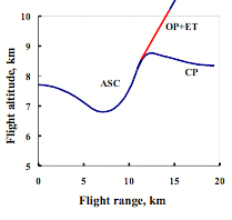
The longitudinal profiles of ASC-OS pull-up trajectory and initial leg of autonomous flight of the carrier-plane and the orbiter with external tank after their separation are shown on Figure 3 (the basic D18T1 version with consideration of oxygen draining in abnormal situations).
|
|
Figure 3. Pull-up maneuver of the MAKS-OS version |
The consideration of the g-load constraints in abnormal entrance of the carrier-plane into horizontal flight at launch failure puts limitation on maximum trajectory angle of the ASC at separation: Θ ≤ 39…40°.
The increment of ASC thrust-to-weight ratio at rocket engines starting before separation allow to use effectively high lift capacity of the carrier-plane when maneuver is performed.
Preliminary analysis of thermal and acoustic influence of LRE jets on the carrier-plane shows that each of two considered modes of LRE functioning (R = 40% и R = 100%) provides safety of the carrier-plane. However, it is preferable to exploit liquid rocket engines at a full thrust since by this way payload mass is increasing by approximately 150 kg and aerodynamic loads on the second stage are reducing by 10…15%.
The Separation of the Carrier-Plane and the Second Stage
The separation process lasting not so much is very complicated and important leg where control of motion of the carrier-plane and the second stage determines safe separation of two flying vehicles. This should be done with a consideration of strength, thermal, acoustic, stability and controllability constraints.
The separation process starts at the moment when trajectory angle at pull-up maneuver is optimal and consists of two phases:
- before mechanical separation – ACS g-load reduction down to a certain negative value nys = -0,5…-0,8;
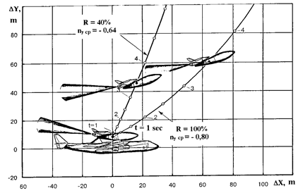
- after mechanical separation – increment of attack angle of the second stage up to 20…25° and carrier-plane flight with negative overload ny cp = -0,6…-0,8.
|
|
Figure 4. The trajectory of relative motion of the MAKS Orbiter with external fuel tank and the Carrier-Plane after separation |
The g-load reduction maneuver of the aerospace complex on the first phase of separation leads to the reduction of trajectory angle thus worsening injection trajectory. That’s why it is necessary to perform this maneuver as fast as possible, but so that not to break constraints on efficiency and operating speed of the elevator as well as constraints on:
- angular pitch speed | omega z | ≤ 10°/s;
- minimal g-load of the carrier-plane at dynamic overload impact after mechanical separation ny min ≥ -1.
Figure 4 shows trajectories of relative motion of the orbital plane with a tank and the carrier-plane at separation with full and reduced rocket propulsion thrust.
To maximize injected mass it is required to increase angle of attack angle of the second stage up to a certain value for minimal time after mechanical separation. The constraint on orientation of LRE jet cone around carrier-plane is considered.
Since a rapid increment of inclination angle of the second stage draws jet to the horizontal tail of the carrier-plane, a delay (~ 2 s) is inserted into control program before angle of attack increment. The dynamics of separation of the MAKS-T, MAKS-M and MAKS-OS versions are practically the same, but each case needs special tuning of control algorithms, for example, tuning of nys and nycp g-loads.
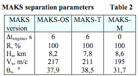
Table 2 presents the following parameters of trajectory for three system versions: Δtengine - duration of rocket engines functioning before separation; R – mode (thrust level) at LRE functioning before separation; Hs, Vs, Θs – flight altitude, speed and trajectory angle in break point.
|
High requirements to control accuracy at pull-up and separation legs cause a necessity of automatic algorithms application.
Injection into an Orbit
Air launch from carrier-plane is distinguished by low level of gravitational losses of characteristic speed if comparing with vertical launch systems. However, the flight in dense layers of atmosphere requires sufficient angle of attack of the second stage and increased loads on construction are achieved. In this connection at the beginning of injection trajectory a control system performs flight with constraints on the following parameters:
- angle of attack alpha ≤ alpha max;
- multiplication angle of attack and dynamic pressure (alpha q) ≤ (alpha q) max;
- aerodynamic load directed normally to the longitudinal axis Yaer ≤ Ymax(М).
The last limitation is given in a form of linear function. The coefficients of this function are determined after complicated analysis of trajectory and constructional loads on the second stage for every MAKS versions.
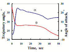
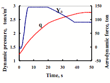
The typical profiles for angle of attack and trajectory angles from time as well as normal aerodynamic force Yaer and dynamic pressure q in the beginning of injection of the orbital plane with tank are shown on Figures 5 and 6.
|
|
Figure 5. The graphs of angle of attack and trajectory angle for MAKS-OS injection |
When the dynamic pressure peak and constraints are passed, control system performs injection into elliptic transfer orbit with minimal fuel mass [2]. For MAKS-OS version the parameters of elliptic transfer orbit correspond to the external fuel tank’s (ET) drop into antipodal area of the World Ocean at approximately 19000 km range from separation point. After ET separation elliptical ascent to given circular orbit is performed. Two two accelerations by the OMS engines is needed for this transition. The same injection scheme is used for a Space Module (SM = space tug + satellite) of the MAKS-T version when a small boost unit (for example, FREGAT-type) is utilized as accelerator for the SM. It guarantees injection into low and middle Earth orbits with altitude up to approximately 5000 km.
|
|
Figure 6. The graphs of normal aerodynamic force and dynamic pressure |
When the MAKS-T configuration is used for a geo-stationary satellite’s injection, the carrier-plane performs flight to the equator above the Pacific Ocean water surface. At this the external fuel tank is not completely filled and its drop takes place at the optimal range of 4000…7000 km, so as full fueling of the geo-stationary boost unit (STORM- or DM-type), used as a third stage, is needed.
The MAKS-M version has not any dropped elements. That is why the terminal state at main engine cut-off (MECO) corresponds to optimal elliptic transfer orbit with perigee altitude of approximately 100 km. In this case to transfer into circular orbit it is required to produce only one accelerating OMS impulse in apogee.
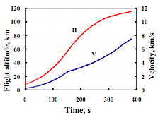
The typical profiles of altitude and flight velocity when the MAKS-OS is injected are shown on Figure 7 for the orbit with 51° inclination.
275 tons take-off mass of the second stage guarantees the following values of payload injected into 51°-inclination orbit: 38,7 ton (for MAKS-M), 37,9 ton (MAKS-OS), 36,9 ton (MAKS-T – the version with FREGAT space tug, upper stage of system).
|
|
Figure 7. The MAKS-OS injection trajectory |
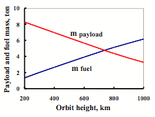
The completely reusable orbital plane of the MAKS-M version is able to inject into reference circular orbit of 51° inclination and 200 km altitude a payload of 5,4…5,5 tons, the MAKS-OS manned version - 8,3…8,4 tons.
The drop of the external fuel tank in partially reusable version not only increases payload mass on low reference orbit, but also provides a low gradient of payload mass decrease in along the orbit altitude thus enlarging the range of system’s application.
Figure 8 presents the OMS fuel mass for inter-orbital transfer (mfuel) and payload mass (mpayload) as a function of the MAKS-OS orbit height (51°-inclination).
|
|
Figure 8. Payload and fuel mass as a function of the MAKS-OS orbit height |
Wide range of achievable orbits of the MAKS-OS (up to 1500 km) is caused by low percentage of dry mass in the total mass of the orbiter injected into reference orbit (see. article ‘Analysis of Various Concepts of the Reusable Space Transport Systems’ of this review).
The MAKS-M orbiter is able to enter an orbit with maximum altitude of only 820 km. Thus, a narrow range of application is a price for completely reusable system.
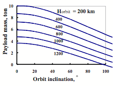
The mobility of a launch from subsonic carrier-plane guarantees expansion of operational orbit inclination range. Available flight distance (parallax) of carrier-plane in the case of its air refueling permits to entrance on required latitude and to inject space vehicles without power-consuming rocket dynamic orbital plane change. Figure 9 shows the payload mass of the MAKS-OS system as a function of orbit inclination i and orbit altitude Horbit. Presented data were received for the condition that a launch takes place at Baikonur latitude φB for high inclination orbits and at latitude equal to inclination if i ≤ φB.
|
|
Figure 9. Payload mass as a function of inclination |
Expandable use of the Transport Module (TM = ET + Main Engine) and boost unit allows to increase payload mass for the MAKS-T cargo version if compared with MAKS-OS and MAKS-M versions, which provide not only injection into orbit but return of payloads from the space to the Earth. The mass of booster unit construction is only a part of total mass of the Space Module injected into orbit. That’s why the MAKS-T version can be used in wide range of orbit altitudes up to geo-stationary ones.
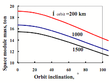
Figure 10 shows space module mass as a function of orbit inclination and altitude when the MAKS-T booster unit of FREGAT type is used. This dependence corresponds to the start of the launch unit from the carrier-plane at latitude φB = 46° for high inclination i > φB and at latitude φ = i when i ≤ φB.
|
|
Figure 10. Space module mass launched by MAKS-T as a function of orbit parameters |
To inject a satellite into geo-stationary orbit it is possible to use booster units (space tugs) of STORM and DM types with increased mass of filling fuel. The optimal transfer into geo-stationary orbit includes acceleration maneuver at approximately 36 000 km altitude performed simultaneously with powered orbital plane turn by an angle equal to the initial inclination i0 or starting latitude of the launch unit from the carrier-plane φ0. Naturally, the nearer to the equator, the less fuel of the booster unit spent at orbital plane change in apogee.
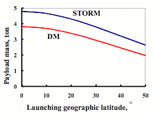
The space vehicle mass on geo-stationary orbit depending on latitude where the launch unit starts from the carrier-plane is shown on Figure 11 for two types of the booster unit. STORM-type booster unit running on ‘hydrogen-oxygen’ components if starting from the equator provides injection of 4,8-ton space satellite into geo-stationary orbit, while DM-type booster unit – 3,8 ton.
|
|
Figure 11. Payload mass launched into geo-stationary orbit by MAKS-T cargo version |
If available parallax without air refueling of the carrier-plane is used, the MAKS-T system is able to inject 3,3-ton space vehicle (the booster unit of STORM-type) and 2,5-tons space vehicle (the booster unit of DM-type) into geo-stationary orbit.
To increase payload mass the MAKS-T version is suppose to execute preliminary (before the end of transport module functioning) drop of the satellite’s cowling. As the Launch Unit (LU = TM + SM) starts eastward, the cowling drops into the Pacific Ocean within 900…1000 km distance from the LU start point. The cowling drop increases payload mass on the reference orbit (i = 51°, Нorbit = 200 km) by approximately 800 kg.
All three version of the MAKS system at the second stage injection leg are suppose to use terminal algorithm of trajectory guidance. This algorithm provides high accuracy of the injection into elliptical orbit at the conditions of following disturbances: atmosphere’s parameters, deviations in aerodynamic, weight and propulsion unit characteristics of the second stage, as well as disturbances in the initial state. Such algorithms are performed on on-board fast digital computer.
At the flight leg with high dynamic pressure it is necessary to use the overload control law, which guarantees to maintain the certain level of aerodynamic load at zone layer wind. It is also supposed to use aerodynamic control devices of the orbital plane to reduce deflection angles of the liquid rocket engines.
The Descend of the Orbital Plane in Atmosphere
The orbital plane of the basic MAKS-OS version has a ‘lifting-body’ aerodynamic configuration with wing panels deflected at 53° from a vertical plane at hypersonic and supersonic descent legs and at 95° at pre-landing maneuvering, landing approach and landing. Such configuration of the orbital plane reduces aerodynamic heat impact on the wing leading edges and guarantees longitudinal balancing in a wide range of hypersonic angles of attack.
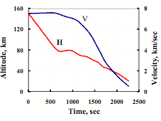
Figure 12 shows profiles of flight altitude and speed from time for typical descent trajectory from reference orbit at hypersonic angle of attack of αhypersonic = 40°.
|
|
Figure 12. Typical descent trajectory of the orbital plane |
Due to a wide range of achievable orbits and variety of solved tasks different requirements could be presented for cross range of the orbital plane descent – up to 2000 km and even more. This circumstance needs to develop flexible algorithms of trajectory guidance. They must provide controllability at hypersonic descent on roll angle as well as on angle of attack if compared with the BURAN control system where hypersonic angle of attack is constant.
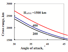
The maximum cross-range (lateral range) of descent as a function of hypersonic angle of attack is shown on Figure 13 for different orbits.
It is should be noted that wide domestic experience in the mechanics of atmosphere flight of winged space vehicles [3, 4] as well as operational experience gained during BOR and BURAN programs can be directly used for the MAKS orbital plane control system development.
Additional experimental data on automatic guidance for descent and landing legs could be received during the MAKS demonstrator flight tests with a consideration of up-to-date on-board control system.
In conclusion it is necessary to indicate that flight performance of the reusable aerospace system guarantee its flexible and operational application in wide range of orbit altitudes and inclinations. Available energy resources of system’s versions allow to inject into space and return onto Earth different payloads and effectively solve wide range of missions appeared in national economy and defense.
|
|
Figure 13. Maximum cross range as a function of hypersonic angle of attack |
References
1. I.V. Ostoslavskaya., I.V. Strazheva. The Flight Dynamics. The trajectories of flight vehicles. - Moscow: MASHINOSTROYENIYE Publishing House, 1969.
2. Filat’ev A.S. The Optimal Space Vehicle Ascent Using Aerodynamic Forces. Cosmic Research, Vol. 29, No. 2. Consultanse Bureau, New York, 1994.
3. L.M. Shkadov, R.S. Bukhanova, V.F. Illarionov, V.P. Plokhikh. The Mechanics of Optimal Spatial Motion of Flight Vehicle in the Atmosphere. - Moscow: MASHINOSTROYENIYE Publishing House, 1972.
4. V.A. Yaroshevsky. Entry into the Atmosphere of Space Flight Vehicle. - Moscow: NAUKA Publishing House, 1988.